RMA Processing Policy and Procedures
Introduction:
The RMA department receives devices that have been authorized by Idrive Support to be returned for repair. The following is the standard procedure for receiving, repairing, and documenting these devices.
The X1 (V5) vs. the X1P (V7):
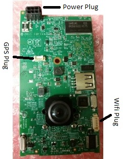
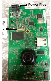
- The easiest way to tell the difference is by the location of the GPS puck. V5 cameras have external GPS units with long black cables. The GPS is internal on the V7 cameras.
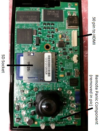
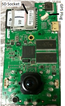
- If examining just a motherboard, the V7 has an HDMI connector, while the V5 has a 50 pin connector. The SD socket is also placed much higher on a V7.
- V5 boards often have a remote panic component that is no longer supported. It should always be removed (see the Remote Panic Component section for more info) as it sometimes causes issues.
- The picture below shows a V5 board that has the component removed manually. Newer versions of V5 motherboards have the component removed by the factory, along with a few other components. Notably, the blue component up and to the right will be missing.
- Both devices have their unique issues and characteristics, but both should operate the same in the end.
The X2:
- The X2 is a completely redesigned board and uses its own test fixture and set of firmware
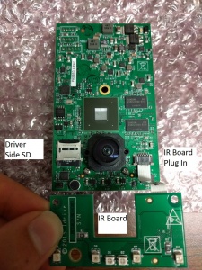
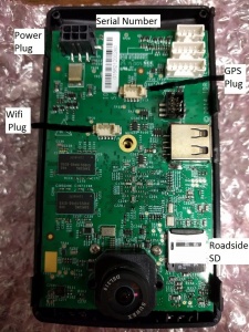
- The Driver's side SD holds the firmware of the unit and should be a 4-8GB Sandisk brand microSD.
- The Road side SD is the main storage of the unit and should be a 32-64GB Transcend brand microSD.
- Any exceptions should be replaced with the correct cards.
The X1 and X1p Test Fixture:
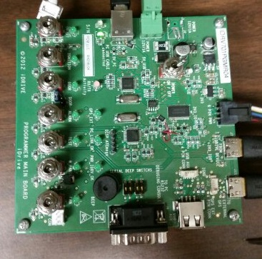
- Connects to devices via power cable and HDMI
- Has switches for all the main triggers that a camera needs (besides shock)
- Power
- Note that the fixture and camera control have separate power switches
- Ignition
- Door
- Alarm
- W. Panic
- Power
- Controls reprogram and firmware update during the RMA procedure
The X2 Test Fixture:
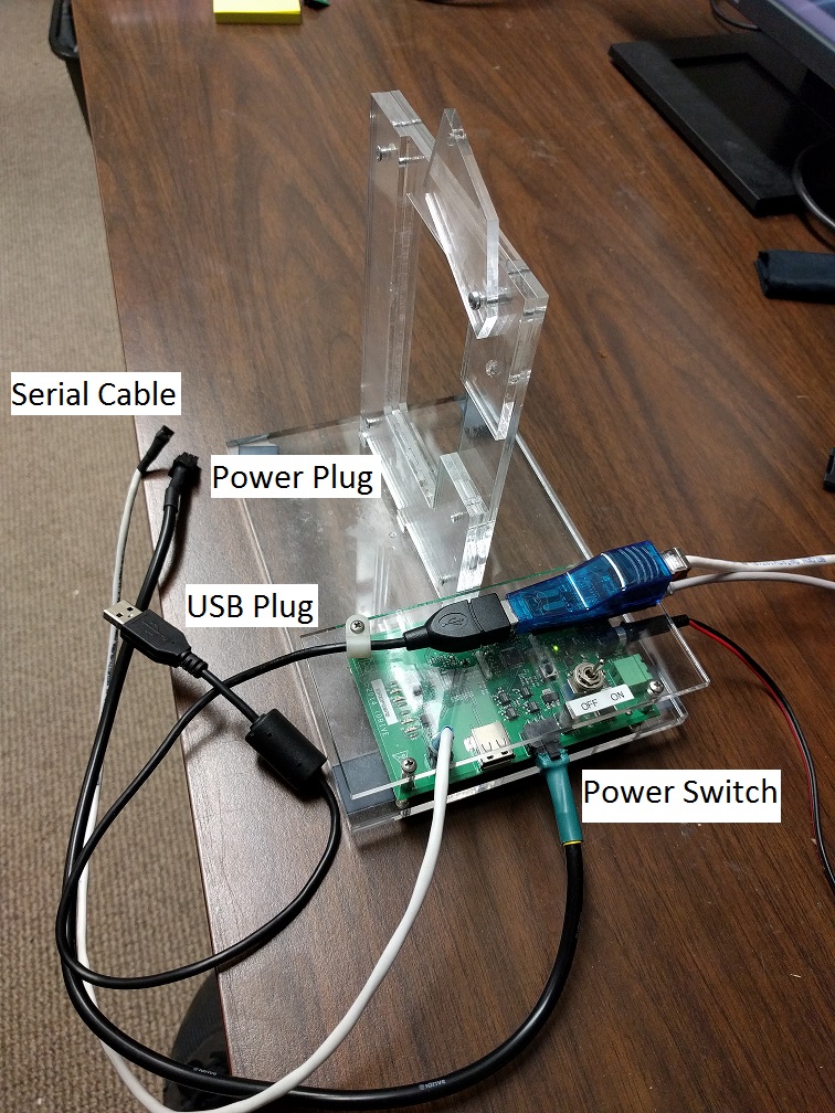
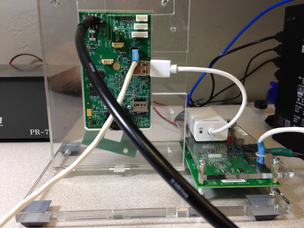
- Connect Power Cable, Serial Cable, USB Cable
- Power On(see power switch on diagram) the fixture before use
Idrive Tools:
- Idrive tools is the software that the test fixture uses to reprogram and update firmware
- The RMA section is what you will primarily be using
- Password: idrive2#rma (no longer has password)
- Enter an existing serial number (the camera you are processing)
- The Parts of the RMA section are outlined in the “For Each Camera” section
- Development section is the same as the RMA section, for the most part. It can be useful at times for testing, as it doesn’t need an existing serial number to run installations. Don’t worry about this now.
- Password: idrive2#dev
Processing:
Visual Inspection:
Check the case and GPS wire for signs of damage and/or tampering.
- Warranty is VOIDED for X1P’s with cases that have been opened.
- Look for missing screws, cracked plastics, etc.
- Cut GPS wires and general damage make a camera “Warranty Damaged” (see Pricing)
(V5) The plastic covering for the GPS puck is often missing. (Do not count this as a plastics repair.)
- Locate new plastics on the shelf above the RMA desk.
- Place the puck in the casing with the dotted side facing the air.
- Snap-in the plastic cover
- Apply a strip of double-sided tape to the plastic cover
(V5) Neatly wrap up the GPS cable and tie it together with a zip tie.
(X2) X2 units that have serial numbers starting with 0258211- will need a component upgrade. Give these to Mark after processing.
(X2) Black cases are out of style and should be replaced by the trendier, more fashionable grey cases. Grey cases have their own mounting brackets. (The black cases warp in high heat.)
Initial Testing:
Test the camera to verify reported issues. Correct LED behavior is outlined here.
- Make sure you have Event Test and Transfer open in Idrive Tools RMA section
- Plug in the power cord
- Turn the test fixture ON
- Turn the switches for power and ignition ON
- After booting, let camera sit in standby mode for 15-30 seconds
- Shake the camera to trigger a shock event
- Turn the switch for ignition OFF to enter transfer mode
- The camera should connect to Idrive Tools
- Transfer entry should turn green if completed successfully
- If a connection is made, play the event that was transferred.
If the camera does indeed have an issue, something should have gone wrong i.e.
- More events than one shock were transmitted
- The camera did not transfer at all
- LED behavior was incorrect
- Lenses were out of focus
With experience, diagnoses can sometimes be made after testing.
Reprogramming(X1):
ALL RMA cameras should be reprogrammed, regardless of their issue or lack thereof.
Take out the motherboard (MB) and ready it for reprogram:
- Unscrew the hex bolt on the back of the case
- Open the case and use the tweezers to undo plastic latches that hold motherboard in place
- Unplug GPS (V5 only) and wifi components
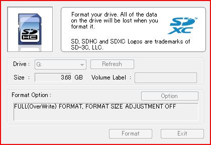
- Remove the SD card and place it in the SD-reader to be formatted (Full-Overwrite mode)
- If the SD Formatter application does not work, try using Windows' built in reformatter
- Go to Computer, right click the removable disk, and select format
- If the SD Formatter application does not work, try using Windows' built in reformatter
- Insert a reformatted SD card that has the filesystem.yaffs and uImage files on it
- Connect the MB to the power cord, (V5) known-working wifi, and HDMI
- Turn the test fixture power ON (all other switches should be off)
Run Idrive Tools.
- Click on RMA or Back to RMA if already open
- Password: idrive2#rma
- Enter in the device serial number (S/N)
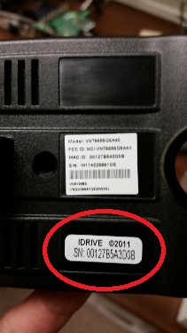
- Will start with 00127B------,01704-------, or 01705-------
- Found on the back of the plastic case (see picture)
- Click on Auto-Install
- Click Start Installation
- The steps the installer follows:
- Bootloader
- Connects via HDMI
- Kernel
- Installs from the SD card (uImage)
- Filesystem
- Installs from the SD card (filesystem.yaffs)
- Device Configuration
- Connects via wifi (V5) or HDMI -> ethernet out of the fixture (V7)
- Lens Focus
- Connects via HDMI
- Bootloader
- The steps the installer follows:
Reconnect the MB to its original GPS and wifi, and unplug the HDMI.
Reprogramming (X2):
Take out the Motherboard(MB) for reprogramming:
- Black Case
- Remove the Phillips head screw on the back of the device (note this screw may be under the serial number sticker)
- Use a pry tool in the USB port opening to separate the case into two halves, and unplug the WiFi and GPS cables
- Un-clip the motherboard from its half by prying at its edges unhooking the plastic clips that hold it in place
- Grey Case
- Remove the four hex or torx head screws from the front corners of the case.
- Separate the case into its three pieces, and unscrew the motherboard from the back panel
- Unplug the GPS and WiFi modules
- Set the case, GPS, and WiFi aside
Inspect the SD cards
- Replace the firmware card (driver's side) with a freshly formatted one loaded with the latest firmware version
- Ensure the storage card (road side) is Transcend brand. Replace any exceptions with new cards of similar capacity. 8GB upgrades to 32GB.
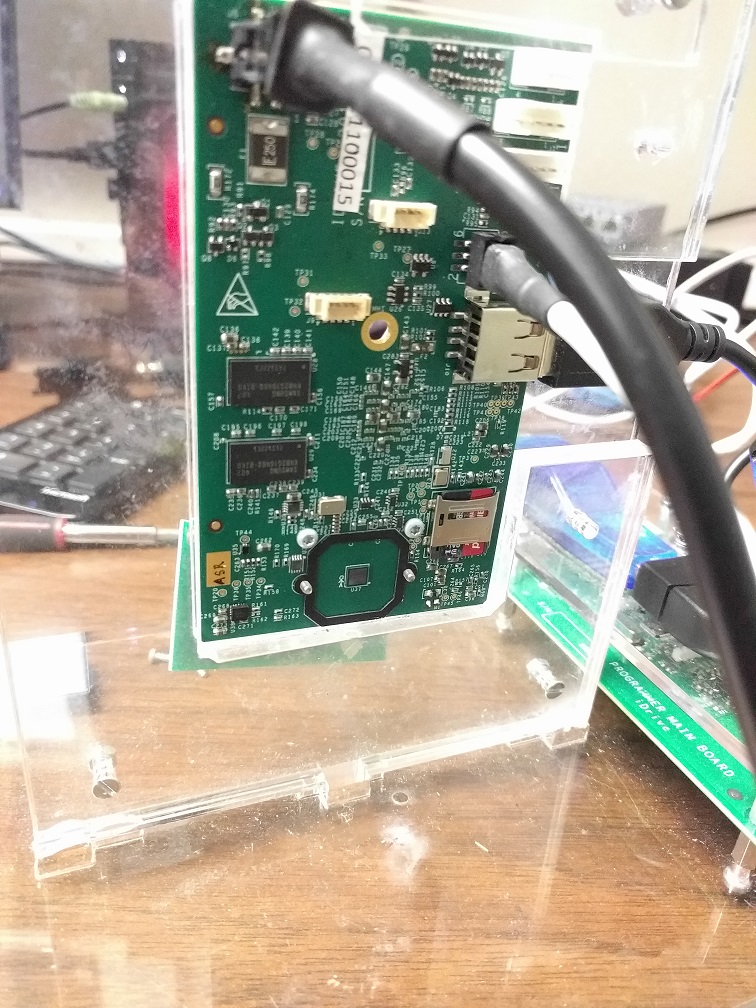
Place the X2 on the test fixture
- Plug in the power chord
- Plug in the serial cable
- Plug in the USB chord
- Make sure the test fixture switch is in the ON position
Run Idrive Tools.
- Click on RMA or Back to RMA if already open
- Password: idrive2#rma (no longer has password)
- Enter in the device serial number (S/N)
- Will start with 0158--------, or 0258--------
- Found on the back/bottom of the plastic case (see picture), also on a label next to the power connector of the MB
- Click on Auto-Install
- Click Start Installation
- When auto install finishes it will show you live video feed images from both lenses with tabs at the top to select individual lenses
Make sure Lenses are properly focused
- Check the focus of each lens using the wall charts
- Drivers side lens should be focused using a chart 3-6 feet away from the camera
- Road side lens should be focused using a chart 9 feet away from the camera
- Check to see if the lenses are securely glued in place
Focus the Lenses(if needed)
- See Lens focus below
Once configured place the MB back into its original case
- Connect the GPS and WiFi wires
- Screw the MB into the back case and secure the IR board on the front case pegs
- Position the middle bracket so that the metal arm rests over the processor of the MB. There are ledges on the bracket that fit under the bottom corners of the MB.
- Join both case halves, sandwiching the middle bracket, and make sure not to block the power plug or USB port with GPS or WiFi wires. Try not to crimp any wires either.
- Screw in case screws
Now you are ready to re-test the device
Diagnosing:
Test the camera again in “Event Test and Transfer". From here, we can diagnose. Below are charts that contain many of the common issues that you will face with both versions of cameras.
| Description | LED Behavior | Fix |
|---|---|---|
| Will not connect in transfer mode (ignition off) | Flashing YELLOW-GREEN | Replace Wifi |
| Camera freezes in standby mode (no triggers, no transfer) | GREEN-GREEN | Replace Wifi |
| Records events without trigger | Flashing RED-GREEN | Replace MB (only if it persists after reprogram) |
| No power | OFF-OFF | Replace MB |
| SD fails reformat or freezes the reformatter | n/a | Replace storage SD |
| Storage Failure | Flashing RED-RED or RED-YELLOW | Replace storage SD |
| Static Audio | Normal | Replace MB |
| Description | LED Behavior | Fix |
|---|---|---|
| Will not boot (reprogram will often change, not fix, this symptom) | RED-GREEN | Usually Wifi, but could also be SD or MB |
| Fails trigger tests during Device Configuration | n/a | Remove remote panic component |
| Goes into transfer mode with ignition ON | Flashing YELLOW - GREEN | Replace MB/remove remote panic component |
| Records panic/remote panic without trigger | Intermittent RED-GREEN | Replace MB/remove remote panic component |
| Repeatedly records shock events (only applicable to newer V5 boards) | Flashing RED-GREEN | Reprogram |
| Description | LED Behavior | Fix |
|---|---|---|
| Will not boot | RED-GREEN | Reprogram |
| GPS continues to fail after unit is changed | normal | Replace MB (bad socket) |
| Video blacks out | normal | Reprogram, then MB if persists |
| Unit does not boot during device config | RED-GREEN | Replace MB |
| Description | LED Behavior | Fix |
|---|---|---|
If the issue you are experiencing is not on this list, troubleshoot the issue by using known-working parts to isolate each component.
Replacing Parts:
See the Policies section for information on Pricing and Not Repairable Diagnosis.
Wifi:
Replacing X1 Wifi(V5, and V7)
- Remove the old wifi and tape from the bracket, discard the unit in the “Bad Wifi Modules” box
- The cable and antenna can be reused, the bracket should only be reused if it is unbent and intact
- Connect the cable to the side of the new module
- Connect the antenna to the input labeled “MAIN” on the back of the module
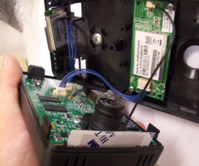
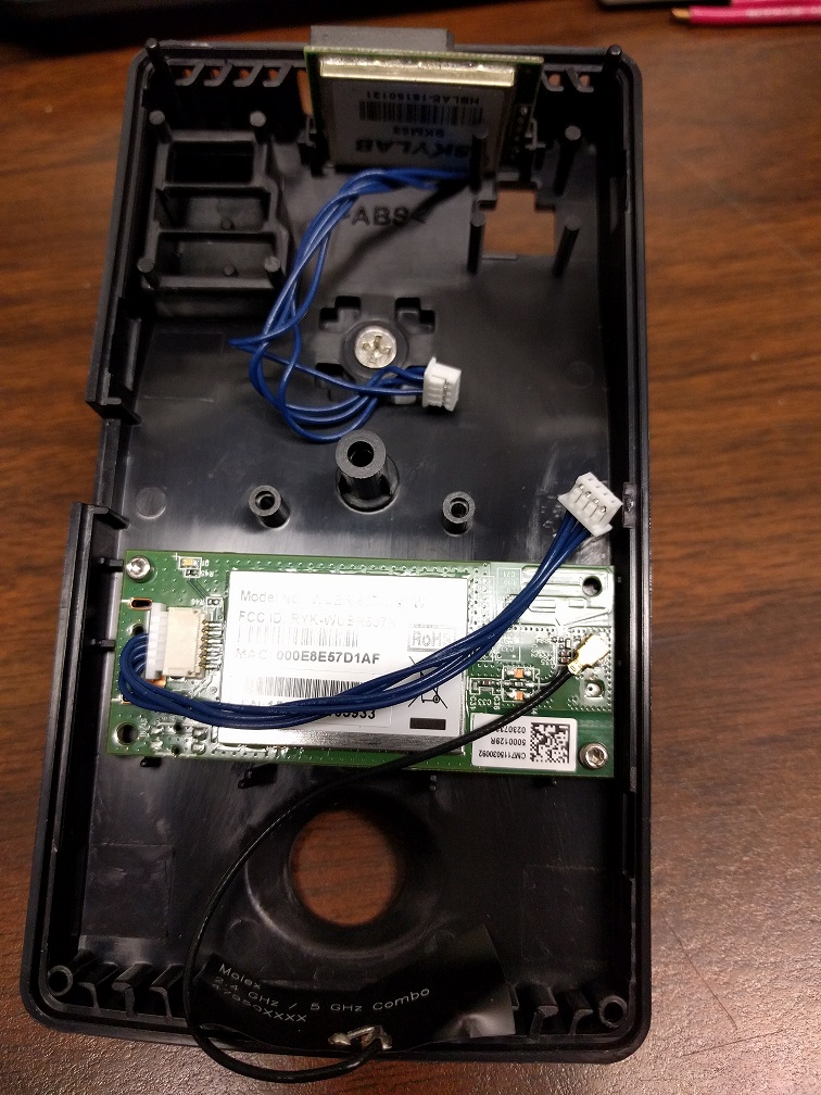
- Orient the circuit board so that the cable socket is facing right when viewed from the back of the bracket (see picture)
- Take the new wifi module and tape it into a bracket from the front of the circuit board, using two pieces of tape as follows (see picture)
- One piece wrapping around the bottom, centered on the square black components
- One piece wrapping around the side, centered on the antenna socket
Replacing X2 Wifi
- Remove the old wifi unscrewing the two screws and washers attaching it(save these)
- remove the Antenna and wifi cable from the old unit inspecting them for damage
- discard the old unit in the “Bad Wifi Modules” box
- Secure the new wifi module with the old screws and washers making sure to attach the wifi cable into its socet and the antenna into the input labeled "MAIN"
- Affix the new wifi antenna end to the bottom of the case as pictured
GPS:
For X2 and X1p(V7) cameras, just replace the unit.
- Note that a rare issue in V7 boards is defective GPS sockets, do not rule out that possibility
For V5 cameras, clip off the tie wrap on the inside of the case if it is there, and remove the cable from the plastics.
- Insert the new cable into the small hole on the top back of the plastics where the old one was
- Tie wrap the inside portion of the cable, leaving about an inch and a half before the connector, and cut off the tail of the tie wrap
- Usually there is a mark from previous tie wraps to go off of
Motherboards:
Replacing X1 and X1p Motherboards
For V5 cameras, this is easy.
- Throw the old motherboard in the e-waste
- Take a replacement motherboard and reprogram it under the desired serial number
For V7, there is a bit of documentation we have to do first.
- Write a note on the old MB with the observed issue before putting to the side. Include the S/N of the replacement MB
- Record the new S/N in all documentation, as it will change to the new number from this point forward
- In Admin Center, unassign the new S/N from Idrive Monitoring Systems - RMA Materials
- Find the old S/N and go to the RMA button
- Leave a note including the new S/N under the tag “Defect”
- Hit the “Replace Device” button and find the new S/N. Accept.
- Assign the old S/N to Idrive Monitoring Systems – Dead or Retired Devices
- Uncheck the dead S/N's final box
- Find the new S/N again and leave an RMA note under the tag “In Factory – Repaired” and include the replaced MB serial
- Run the new MB through Auto Install using the new S/N
Replacing X2 Motherboards
- Write a note on the old MB with the observed issue before putting to the side. Include the S/N of the replacement MB
- Record the new S/N in all documentation, as it will change to the new number from this point forward
- In Admin Center, unassign the new S/N from Idrive Monitoring Systems - RMA Materials
- Find the old S/N and go to the RMA button
- Leave a note including the new S/N under the tag “Defect” saying "Replaced by:The new motherboard's SN"
- Hit the “Replace Device” button and find the new S/N. Accept.
- Assign the old S/N to Idrive Monitoring Systems – Dead or Retired Devices
- Uncheck the old S/N's final box
- Find the new S/N again and leave an RMA note under the tag “In Factory – Not Repaired” and include "Replaced MB: the replaced MB serial"
- Run the new MB through Auto Install using the new S/N
- Make sure to print the new Serial Number label and affix it over the case screw in the testing phase
Remote Panic Component(X1 V5):
Section commented out, this repair is outdated and any applicable boards should be labeled Not Repairable.
Lenses:
X1 and X1p (V5 and V7) Most of the time, a lens that is out of focus can be screwed in or out back into focus. Once in focus, superglue the lens in place.
If the lens is broken, out of focus, etc. and is stuck glued into the bracket, then you must remove the whole lens bracket from the motherboard.
- Find a suitable screwdriver (the screws are either small phillips or torx)
- Remove the screws on the opposite side of the board that hold the black plastic lens bracket in place.
- Replace with a new lens and bracket found on the shelf above the RMA desk
- Note both sides of the X1 and X1p cameras use the same lens
X2 Lenses
If the lens is loose
- Focus it using the hung X2 focusing Charts
- For Road side Lenses(say sunex on the bezel) focus it to the length of 9 feet
- For Driver side Lenses(have no writing on the bezel) focus it to the length of 3-6 feet
- Glue the lens using Super Glue
If the lens is glued out of focus
- Tighten the fastening screws on the lens holder and see if the focus changes
If the Lens is still out of focus Replace the lens
- Remove the lens holder since it will be impossible to break the lens glue without incurring damage to the lens
- Replace the lens holder and lens
- Place gasket on X2 Motherboard locating it with the two small phillips head screws, then use those screws to secure the metal replacement lens holder
- Focus the new lens to the appropriate length(see "If the lens is loose" above for focus lengths)
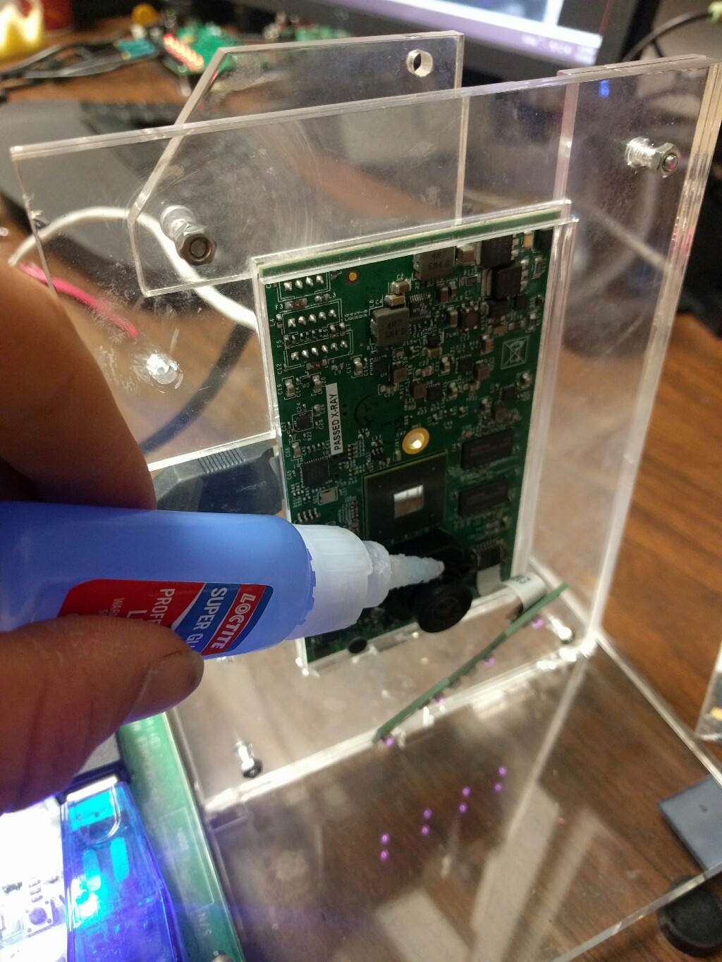
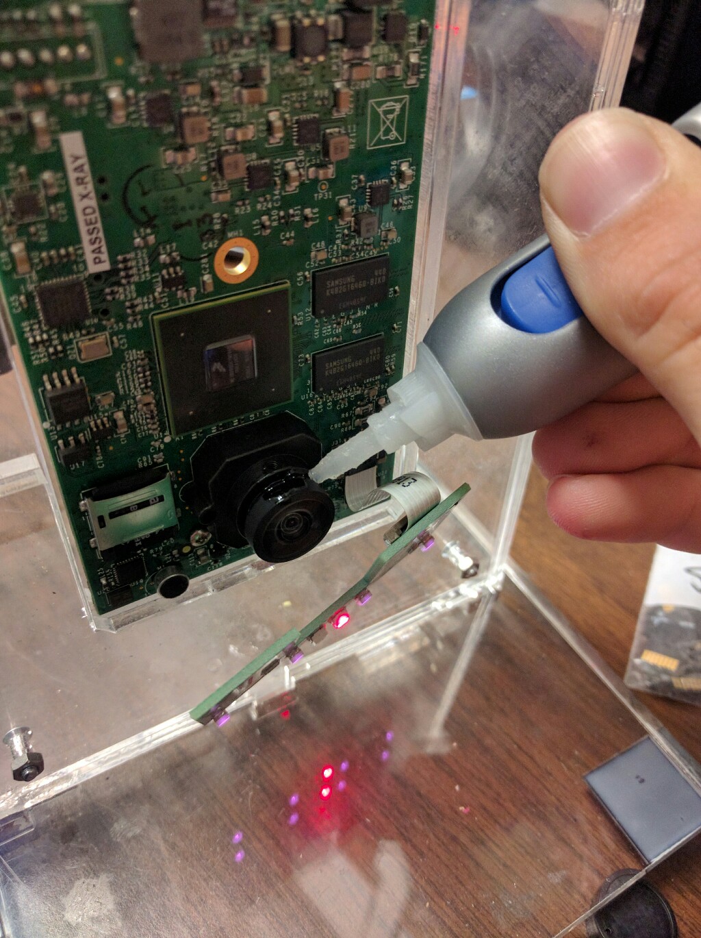
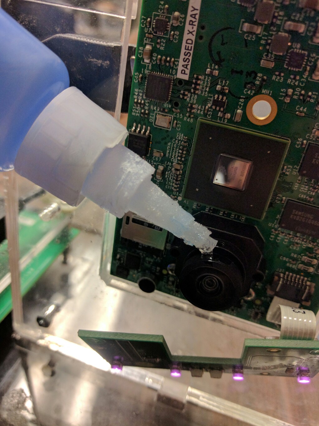
- Apply a small dab of loctite professional liquid super glue (This is the blue bottled glue that is a liquid and cures in 5 seconds)
- Apply a larger dab of loctite gel control super glue to fill the gap between the lens and its holder (This is the silver and white bottled glue that is in a gel form and takes 24 hours to cure)
- Allow the glue to cure overnight, resting it upright against a wall labeling it with a post it for easy identification
- Be sure to leave the motherboard out of its case(this is because the glue releases gas that can damage the case)
- Make sure the focus hasn't changed after the lens glue has been cured by assembling and final testing the camera
Documentation:
There are three places that you need to log the information from an RMA.
Shipping form:
Download “New RMA Shipping Form” here. Use this as your template.
- Fill in the necessary information specific for the customer
- Enter the S/N's of the cameras in the RMA in the designated fields
- Select repairs from the drop down lists in each section of the table
- See the Policies section for information on Pricing and Not Repairable Diagnosis
Print 2 copies of this form for the box(es) to be shipped, and create a .pdf version to email to finance (if there are no charges) or to the customer (if there are charges). See Policies for exceptions. When emailing a customer, follow the template and check the applicable boxes with an "X". Subject line convention is "Idrive RMA <Customer Name> <Location> <RMA Number>".
Be sure to copy support@idriveglobal.com on all emails.
Special Cases:
- X1P and X2 MB replacements
- include a note in the Repair Needed field that says "S/N Changed to <New S/N>"
- Highlight it in black, and change the text color to white
- Attach a physical note to the camera citing old and new S/N (Download template)
- Not Repairable cameras
- Select "Not Repairable (see comment below)" for the Repair Needed field
- Find the comments box at the bottom and select the second option from the drop-down list
- "One or more of your Device(s) has been diagnosed to be Not Repairable..."
RMA Log:
On the network at \\IDR1\Users\Idrive_support\Support you will find a file called “RMA Log”.
Fill in the spreadsheet for the specific RMA in three parts:
- When the RMA is issued via email, add the device S/N’s, RMA #, date, customer name, reported issues, and any special conditions to the RMA Log spreadsheet
- When the RMA is received, enter the date in the Received Date field
- After the RMA is performed, fill in the remaining information
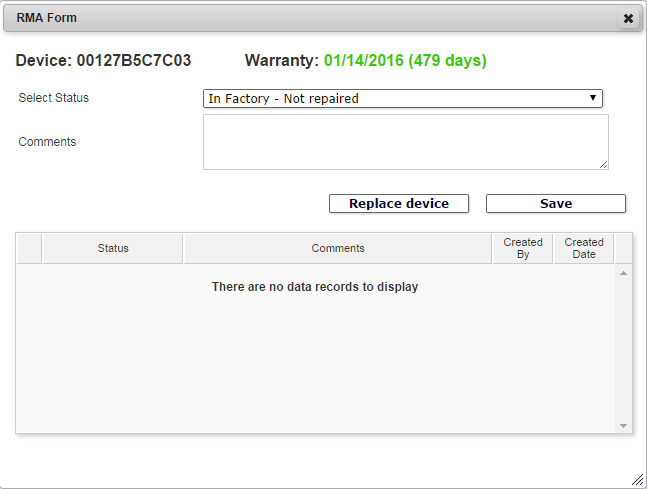
Admin Center:
Look up each device in the Admin Center. For each:
- Click the RMA button
- Change the RMA status to “In Factory – Repaired”
- Add a comment that outlines repairs made
- Save
If the device is Not Repairable:
- Change RMA status to “Defect”
- Add a comment “Not Repairable from <customer>”
- Save
- Unassign the device and reassign it to "Idrive Monitoring Systems - Dead or Retired Devices"
- Uncheck the final box
Policies:
Pricing:
A downloadable spreadsheet of processing fees is available here.
Packaging:
Proper packaging is vital to the safety of cameras due to the rough way packages are typically handled.
After processing an RMA...
- Place each camera into a ziplock bag (We have special red ones that are anti-static)
- Note: X1P's without mounting brackets can fit horizontally
- Place each bagged camera into a bubble wrap bag (Again, special red ones)
- Note: X1P's without mounting brackets can fit horizontally
- We have white boxes in the back specifically for X1's
- Distribute no more than 4 cameras per box
- On right side of the box, write some RMA information
- (Top Left) RMA #(s)
- (Center) Customer Name and Location
We expect customers to provide the same level of safe packaging, so badly packaged RMA's are subject to becoming In Warranty, Damaged.
Not Repairable Diagnosis:
When a camera is marked "Not Repairable," we salvage it for parts and provide a discount to the customer to buy a new camera as a replacement.
There are a few ways in which a camera can be diagnosed as Not Repairable.
- The camera was returned severely physically damaged
- (V5) The camera's board version is less than or equal to 5.10 (subject to change over time)
- Three different repairs (exclusively including a MB) were needed on the camera at once
- The cost of repair was over $300
- Any V5 not from Storer or RMS is automatically Not Repairable
Customer-Specific:
Clark Pest Control:
- No charge for In Warranty V5 MB's through the end of 2014 (until further notice 2/18/2015)
- All out of warranty X1 cameras will be replaced by a new X2 per Cyrus Cortez's request
- All RMA's are sent back to Corporate--Clark Pest Control, 555 N Guild Ave., Lodi, CA 95240
- For this reason, multiple RMA's from different locations can all be shipped at once
- Billing prefers for shipping forms that include multiple RMA's be separated in some way
- For this reason, multiple RMA's from different locations can all be shipped at once
Storer Bus:
- Contact Sean before doing just about anything high-cost or questionable with Storer
- We have a deal with Storer to repair all Out-of-Warranty devices (regardless of age) for $50 + cost of parts.
- Send all charges to Steven Fernandes.
RMS (Rail Management Services):
- We send packing materials to RMS for them to return their devices with.
- RMS is a "ship with charges" client. Send shipping forms straight to finance.
- Contact Curt before sending large bills or assessing cameras as non repairable
- We treat RMS with white gloves as they are a huge customer for us and pay us extra for additional support services.
Parsec (LA and LPC)
- Parsec is a "ship with charges" client. Send shipping forms straight to finance.
- Contact Curt before sending large bills or assessing cameras as non repairable
- If large batch of out of warranty cameras contact Curt before repairs are made, he usually gets them to upgrade to the latest cameras
Antonini:
- All RMA shipments are to be sent back to the headquarters at the Lathrop location
Gulfmark:
- All RMA shipments are to be sent back to the headquarters at the Corporate location
