Dunbar Armored Vehicle Installation Guide
WIRING INFORMATION TO INSTALL I-DRIVE CAMERAS IN DUNBAR ARMORED TRUCKS
1990-1997 Internationals Wiring Locations
"Battery" Power: The Battery Power connection "RED WIRE" will be made inside the power distribution panel located on the driver's side forward door pillar.
Ignition Power: The Ignition Power connection "WHITE WIRE" will be made inside the power distribution panel located on the driver's side forward door pillar.
Ground: The Ground connection "BLACK WIRE" will be made inside the power distribution panel located on the driver's side forward door pillar.
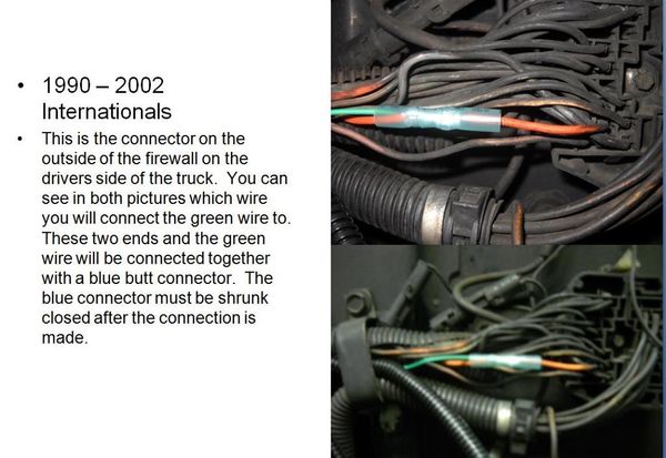
Backup Alarm: The "GREEN WIRE" for the back up alarm trigger will be connected outside of the firewall on the driver's side bulkhead connector. Please see the attached picture.
Passenger Door Trigger: The "YELLOW WIRE" for the passenger door trigger will be connected to the passenger door indicator light inside of the Master Box that is mounted to the left of the steering wheel.
Panic Button: The "Panic Button" will be mounted on the Master Box that is mounted to the left of the steering wheel. This connects to the "BLUE WIRE" from the Camera harness and the other wire from the Panic Button goes to ground.
1990-1997 Internationals Wiring Picture
1998-2002 Internationals Wiring Locations
"Battery" Power: The Battery Power connection "RED WIRE" will be made inside the Master Box located on the driver's side door pillar. We have found a few trucks that did not have power in the Master Box. If that is the case, you can get power from the power strip that is mounted on the left kick panel. Master Box should be used first.
Ignition Power: The Ignition Power connection "WHITE WIRE" will be made inside the Master Box located on the driver's side door pillar.
Ground: The Ground connection "BLACK WIRE" will be made inside the Master Box located on the driver's side door pillar.
Backup Alarm: The "GREEN WIRE" for the back up alarm trigger will be connected outside of the firewall on the driver's side bulkhead connector. Please see the attached picture.
Passenger Door Trigger: The "YELLOW WIRE" for the passenger door trigger will be connected to the passenger door indicator light inside of the master box that is mounted to the left of the steering wheel.
Panic Button: The "Panic Button" will be mounted on the Master Box that is mounted to the left of the steering wheel. This connects to the "BLUE WIRE" from the Camera harness and the other wire from the Panic Button goes to ground.
2004-2007 Internationals Wiring Locations
"Battery" Power: The Battery Power connection "RED WIRE" will be made inside the Factory Fuse panel located on the passenger side of the dash board. There is a "red" wire supplied by International Trucks that is used for connecting auxiliary equipment such as mobile phones. These wires may have low amperage draw equipment connected to these wires already, but there is still sufficient power and amperage available to use this wire.
Ignition Power: The Ignition Power connection "WHITE WIRE" will be made inside the Factory Fuse panel located on the passenger side of the dash board. There is a "pink" wire supplied by International Trucks that is used for connecting auxiliary equipment such as mobile phones. These wires may have low amperage draw equipment connected to these wires already, but there is still sufficient power and amperage available to use this wire.
Ground: The Ground connection "BLACK WIRE" will be made inside the Factory Fuse panel located on the passenger side of the dash board. There is a "white" wire supplied by International Trucks that is used for grounding auxiliary equipment such as mobile phones.
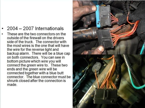
Backup Alarm: The "GREEN WIRE" for the back up alarm trigger will be connected outside of the firewall on the driver's side. There is a connector located above or to the side of the Power Distribution Center located on the driver's side on the firewall. Please see the attached picture.
Passenger Door Trigger: The "YELLOW WIRE" for the passenger door trigger will be connected to the passenger door step light. The yellow will be run to the right of the fuse panel along the passenger side kick panel. A 3/8" hole will be drilled in the floor where the firewall meets the floor on the passenger side of the truck. The yellow wire will be run outside of the cab and down under the floor but behind the passenger fender extension and connected to the power wire for the passenger door step light.
'Panic Button: The "Panic Button" will be mounted on the Master Box that is mounted to the left of the steering wheel. This connects to the "BLUE WIRE" from the Camera harness and the other wire from the Panic Button goes to ground.
2004-2007 Internationals Wiring Picture
2011 & Newer Dodge A-Bodies Wiring Locations
"Battery" Power: The Battery Power connection "RED WIRE" will be made inside the Windshield Power Box located above the windshield frame in the center of the truck.
Ignition Power: The Ignition Power connection "WHITE WIRE" will be made inside the Windshield Power Box located above the windshield frame in the center of the truck.
Ground: The Ground connection "BLACK WIRE" will be made inside the Windshield Power Box located above the windshield frame in the center of the truck.
Backup Alarm: The "GREEN WIRE" for the back up alarm trigger will be connected directly on the backup alarm. It will be necessary to run a wire all of the way to the backup alarm mounted at the rear of the truck. Under no circumstances is a wire to be cut under the chassis to try connecting the backup alarm circuit.
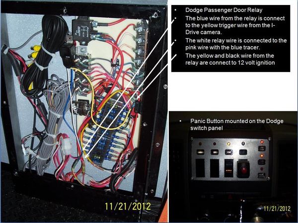
Passenger Door Trigger: The "YELLOW WIRE" for the passenger door trigger will be connected to a relay inside the power distribution center located behind the driver's seat. The yellow wire will be run behind the "Z" channel above the windshield to the left. It will continue behind the "Z" channel above the driver's door. Where the "Z" channel meets the bulkhead behind the drivers seat the yellow wire will go thru the hole on the left wall and continue down the wall and will exit out of the wall at the opening near the floor and follow the existing wiring bundle into the power distribution center. The "PINK WIRE" with "BLUE" tracer is the ground wire for the passenger door switch and will be used to open and close the relay that will provide the 12 volts needed for the passenger door trigger.
'Panic Button: The "Panic Button" will be mounted with the switch cluster in the center of the dash board. This connects to the "BLUE WIRE" from the Camera harness and the other wire from the Panic Button goes to ground.
2011 and Newer Dodge Wiring picture Internationals Wiring Picture
SOME IMPORTANT NOTES
- All wires will be run in plastic split loom.
- All wire connections will be made with shrink connectors, and all connectors will be shrunk when the job is complete. This includes all connections made inside of the cab area.
- All wires will be secured using wire ties. There should be no more then 12" between wire ties.


