Stonkam D8 Installation Guide
Idrive D8 Installation Guide
Packaging
The DVRs will be programmed for a specific individual vehicle. This way when received by the installer the DVR will be set up for the exact vehicle and configuration. The outside of the DVR Box will have the vehicle number on it.
- Camera and Cable Kits will be packed in separate box. (Only the DVR is vehicle specific however the Crane package will be different and marked accordingly)
- Each location (not DVR) will receive a Monitor, Extra Hard Drive, Hard drive reader, A few remote controls and sets of keys.
System Components
Idrive D8 DVR
- DVR with SSD & SIM card installed and configured for specific vehicle
- Security Shield
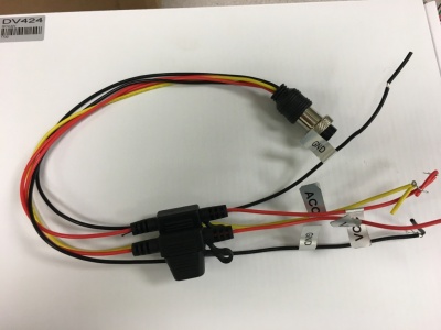
- Power Cable and Fuse
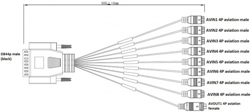
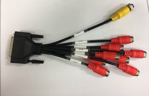
- 44Pin Camera Breakout Cable
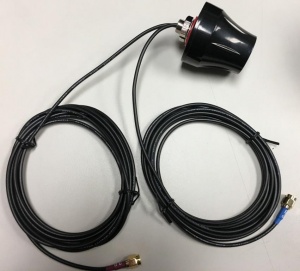
- Dual 3G/GPS Antenna
- Keys
- Remote Control (Batteries Installed)
Camera Types
- IDRDVRWPRCAMDIN - Waterproof Rear View CAM
- IDRDVRD4CAM1 - Standard CCD Dome Cam (No Audio)
- IDR8165CAM - 155 degree view
Video Splitter (Single channel)
For use in Cranes only to route the video from the existing 4 camera monitor system to the DVR.
- QTY 4 Video Splitters (1 for each existing ECCO Camera)
- Each Splitter has 3 adapter cables
- Splitter to DVR
- Splitter to ECCO Camera
- Splitter to Monitor
- Four 3 meter extension cables (from Splitter to DVR)
Monitor
One Per Location
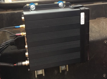
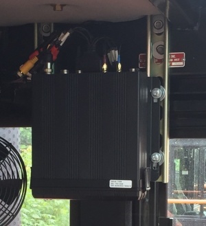
Mount the DVR in the vehicle
Connections
Before Installations on cranes verify that the existing installed equipment is functioning. Idrive is not responsible for the 4 installed cameras or monitor system on cranes.
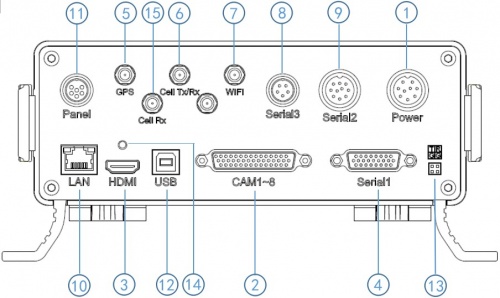
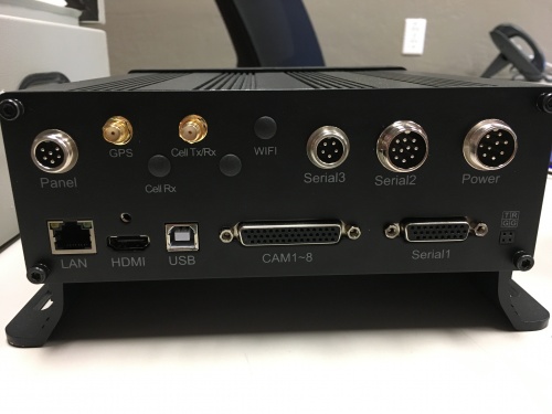
Back Panel Diagram
| Back Panel Connections | |
|---|---|
| 1) Power input (12-32V) | 9) Panic button, external GPS module connector |
| 2) Camera cable input | 10) Ethernet(RJ45) |
| 3) HDMI output | 11) 6pin CVBS video monitor output |
| 4) Alarm input/output | 12) USB 2.0 input |
| 5) GPS Connector | 13) debug |
| 6) Cellular Connector, TX/RX | 14) HDMI cable fixing hole |
| 7) Wifi Connector | 15) Cellular Diversity Connector, Rx |
| 8) Can input/output, External temp.sensor input |
Power
Power Cable
- *Red +12volts
- *Black GROUND
- *Yellow Ignition
Pin 1 : VCC
Pin 2 : VCC
Pin 3 : IGN
Pin 4 : NC
Pin 5 : NC
Pin 6 : GND
Pin 7 : GND
Pin 8 : NC
Pin 9 : NC
Fuses are 5 AMP
Power Connections
Changed 8/29/17: ACC now hard wired to power through fuse (no switch)
ACC (Yellow wire) connected to power with no switch (DVR Always on)
Cameras
44 Pin Camera Cable
Camera Connections
| Camera Connections | Cam#/Type/Cable | ||
|---|---|---|---|
| Connector | Side Loader | Chassis Handler | Crane |
| AVIN1 | #1 /Dome/ 5m | #1 /Dome/ 5m | #1/Dome/5m |
| AVIN2 | #2 /WP/ 10m | #2 /WP/5m or 10m? | #2/WP/10m |
| AVIN3 | #3 /WP/ 10m | #3 /WP/ 10m | #3/WP/10m |
| AVIN4 | #4 /WP/ 10m | #4 /WP/ 10m | #4/WP Wide Angle/65m with Vbooster module |
| AVIN5 | N/A | N/A | #5 /Splitter CH1/ 3m |
| AVIN6 | N/A | N/A | #6 /Splitter CH2/ 3m |
| AVIN7 | N/A | N/A | #7 /Splitter CH3/ 3m |
| AVIN8 | N/A | N/A | #8 /Splitter CH4/ 3m |
Mounting Locations
Side loader Camera Locations & Mounting
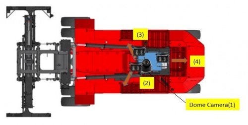
- #1 Dome Cam mounted above and to the Left of driver On screen name: CAB
- #2 Waterproof Cam On screen name: L-Front
- #3 Waterproof Cam On screen name: R-Front
- #4 Waterproof Cam On screen name: Rear
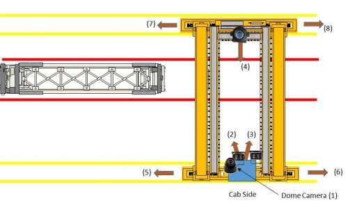
Crane Camera Locations & Mounting
- #1 Dome Cam mounted above and to the Left of driver On screen name: CAB
- #2 Waterproof Cam On screen name: L-Front
- #3 Waterproof Cam On screen name: R-Front
- #4 8165 Cam On screen name: Far-Side
- #5 - Existing installed camera On screen name: CH5
- #6 - Existing installed camera On screen name: CH6
- #7 - Existing installed camera On screen name: CH7
- #8 - Existing installed camera On screen name: CH8
GPS/3G Antenna
Video Monitor
7" Monitor
Configuration is done for each specific vehicle at Idrive prior to shipment.
We supply a standard regular monitor for customer locations to be used for video playback.
Plug into Video Out (Yellow 4 Pin Connector) on the 44Pin Cameras cable using the Male to Male adapter and cable.
Video Splitter (Cranes only)
For the Crane installs. It splits the video from the existing installed camera into 2 signals. One goes to the existing monitor system and the second to the Idrive D8.
The Monitor system supplies power to each channel individually so that if the Idrive D8 is shut off or has some issue the Existing monitor system will keep working.
More Picture and information will follow in a few days.
Size and Mounting Area
Mounting Location
Each Splitter should be mounted where the Camera cable connects to the existing monitor system cable. The adapter cables all all that should be needed for this. Each adapter cables ~12" long.
Adapter Cables
3 different adapter cables are supplied and each is 300CM long.
Functional Test and Sign Off
- Connect Monitor to system
- Power On system
- Verify video for all channels is working (4 channels for loaders, 8 channels for cranes)
- Verify the cameras are upright and pointed at the correct location
- Contact Idrive Support 805-273-4196 to confirm the DVR is registered on the server
- Verify GPS
- Verify Cellular conection
- Turn Keys and Remote control over to terminal manager
- Manager sign off sheet for installation complete
