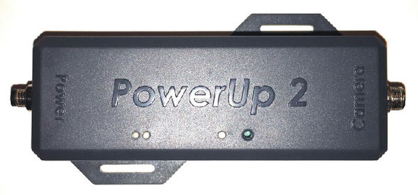
PowerUp2 Installation and Operation and Specifications Guide
Copyright information
This document contains proprietary information that is protected by copyright. No part of this document may be photocopied, reproduced, or translated to another language without the prior written consent of Idrive Inc. Copyright © 2020 Idrive Inc.
This product incorporates copyright protection technology. Use of this copyright protection technology must be authorized by Idrive Inc. Reverse engineering or disassembly is strictly prohibited. Information in this document is subject to change without notice.
Warnings
Please read the following carefully regarding proper use of the product and ensuring the user’s safety.
1. Use the idrive device only for its intended purpose.
2. Do not disassemble, attempt to repair, or alter the Idrive device. When malfunctions, errors, or other damage is found to be attributable to a user, said user may not be eligible for after sale service.
3. When cleaning the inside of a vehicle, do not spray water or any other cleaning product directly onto the Idrive device. It may cause damage, fire, or electric shock.
4. Keep the Idrive device away from chemicals or detergents as they may change the surface of the product or ruin internal components.
5. Do not insert any foreign objects into the Idrive device. Severe impact, shock, or other foreign matter may cause damage to the Idrive device.
6. Make sure the product is installed securely and do not expose the device to excessive shock. Do not move the device after installation.
7. Keep the product away from excessively humid or salty environments.
8. Use ONLY the supplied cable to connect the Idrive device to the power source, and only as directed in the manual. This product should be connected only to the power inside a vehicle. Any other power source is unacceptable and may cause malfunction or fire and may render the Idrive device ineligible for after sale service.
- The information contained in this technical manual may be accompanied by omissions, Idrive Inc., reserve the right to make further changes.
- Idrive Inc., does not authorize the use of the systems for medical purposes or the saving of human lives.
Idrive PowerUp2
DESCRIPTION
The PowerUp 2 is a high voltage power manager providing instant-on operation and high efficiency battery charging over a wide voltage range.
- Seamlessly used for 12Vdc to 24VDC embedded automotive systems; e.g. X2 & AI Camera Event Video Recording Systems.
An onboard buck-boost DC/DC controller operates with battery and/or system voltage above, below or equal to the input voltage.
- The PowerUp2 seamlessly manages power distribution between battery and converter outputs in response to load variations,
battery charge requirement and input power supply limitations.
- The module instant-on operation ensures system load power even with a fully discharged battery.
- Additional safety features include preconditioning for heavily discharged batteries and an integrated timer for termination
and protection.
- The module can provide constant-current/ constant -voltage charge algorithm
(CC/CV). Maximum converter and battery charge current are resistor controlled.
- Directional Male/Female connector and cables are provided for quick-connect to AI Camera and insertion of PowerUp2 quickly, without the need for additional wire connections
- Min. 35 Minute Power Back-up for AI at 350mA/h current consumptions
Technical Specs
FEATURES
- Wide Voltage Range: 8Vdc – 38Vdc, Up to 55Vdc
- Voltage Output 13.3Vdc – 15.6Vdc
- Maxim Current Output 1.65Adc
- Easy connect or disconnect from AI camera system
- Synchronous Buck-Boost DC/DC Controller
- LI-Po Charge and Protection Algorithms
- +/- 0.5% Float Voltage Accuracy
- +/- 0.5% Float Current Accuracy
- Instant-On for Heavily Discharged Batteries
- Ideal Diode Controller Provides Low Loss
- Power Path When Input Power is Limited
- Onboard Timer for protection and Termination
- Bad battery Detection with Auto-Reset
- NTC Input for Temperature Qualified Charging
- Binary Coded Status LEDs
- Battery Used Li-Po 500 mA, 14.8Vdc
- Min. 35 Minute Power Back-up for AI at 350mA/h current consumptions
ABSOLUTE MAXIMUM RATINGS
Maxim input voltage range | 55Vdc
Maxim input voltage operating range | +8 - +38Vdc
Automotive TVS for low dump protection (LDP01-42AY) | +42Vdc
Reverse polarity protection | yes (50Vdc)
Maximum operate sink current 2.5Adc
PTC overcurrent protection | 2.5Adc(25°C)
Maximum input voltage for all signals input | +/-65Vdc
Maximum input operating voltage for all signal input | +55Vdc /-0.6Vdc
LEDs and Status Test Button
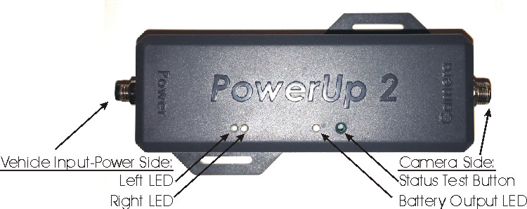
The PowerUp2 contains 2 LEDs (ED1 red, ED2 green) that provide charger status and signals fault conditions
status. These LEDs binary coded signals:
- Battery charging
- Standby or shutdown modes
- Battery temperature fault
- Bad battery fault (unfulfilled preconditions)
Also, the system contains another bicolor led (ED3 red and green) that provide actual functional mode:
- Powered by VBAT GREEN
- Powered by internal VBAT1 RED
Vehicle Input-Power Side
Status, State LEDs and Charging Conditions
| Power LEFT LED | Power RIGHT LED | CHARGING CONDITION |
|---|---|---|
| LED OFF | LED OFF | Not charging–Standby |
| LED OFF | LED ON RED | Battery Fault |
| LED ON GREEN | LED OFF | Charging Cycle OK; Trickle Charging |
| LED ON GREEN | LED ON RED | Battery Thermal Sensor Shutdown |
Camera Side
| Output LED | Operation Mode | OUTPUT CONDITION |
|---|---|---|
| GREEN | Powered By Vehicle Batt | VBAT>= 12Vdc & VOUT>=12.5Vdc only,
else GREEN OFF |
| RED | Powered by Internal Batt | RED if current source>280mA on VOUT only,
else RED off |


