RMA Processing Policy and Procedures
Introduction:
The RMA department receives devices that have been authorized by Idrive Support to be returned for repair. The following is the standard procedure for receiving, repairing, and documenting these devices.
The X1 (V5) vs. the X1P (V7):
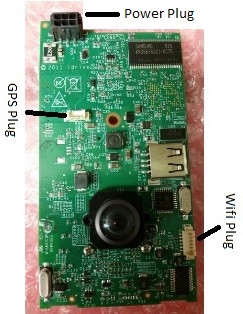
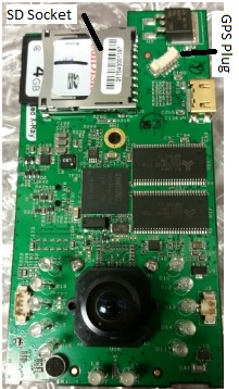
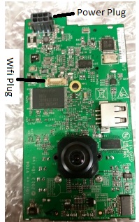
- The easiest way to tell the difference is by the location of the GPS puck. V5 cameras have external GPS units with long black cables. The GPS is internal on the V7 cameras.
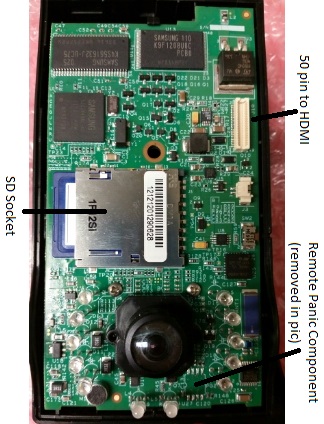
- If examining just a motherboard, the V7 has an HDMI connector, while the V5 has a 50 pin connector. The SD socket is also placed much higher on a V7.
- V5 boards often have a remote panic component that is no longer supported. It should always be removed (see Replacing Parts section for more info) as it sometimes causes issues.
- The picture below shows a V5 board that has the component removed manually. Newer versions of V5 motherboards have the component removed by the factory, along with a few other components. Notably, the blue component up and to the right will be missing.
- Both devices have their unique issues and characteristics, but both should operate the same in the end.
The Test Fixture:
- Connects to devices via power cable and HDMI
- Has switches for all the main triggers that a camera needs (besides shock)
- Power
- Note that the fixture and camera control have separate power switches
- Ignition
- Door
- Alarm
- W. Panic
- Power
- Controls reprogram and firmware update during the RMA procedure
Idrive Tools:
- Idrive tools is the software that the test fixture uses to reprogram and update firmware
- The RMA section is what you will primarily be using
- Password: idrive2#rma
- Enter an existing serial number (the camera you are processing)
- The Parts of the RMA section are outlined in the “For Each Camera” section
- Development section is the same as the RMA section, for the most part. It can be useful at times for testing, as it doesn’t need an existing serial number to run installations. Don’t worry about this now.
- Password: idrive2#dev
Processing:
Visual Inspection:
Check the case and GPS wire for signs of damage and/or tampering.
- Warranty is VOIDED for X1P’s with cases that have been opened
- Look for missing screws, cracked plastics, etc.
- Cut GPS wires and general damage make a camera “Warranty Damaged”
- Treat the camera as if out of warranty for this particular RMA, but once returned the warranty is back to normal
- X1 units with open cases are automatically “Not Repairable”… more on that later
Initial Testing:
Test the camera to verify reported issues. Correct LED behavior is outlined here.
- Make sure you have Event Test and Transfer open in Idrive Tools RMA section
- Plug in the power cord
- Turn the test fixture ON
- Turn the switches for power and ignition ON
- After booting, let camera sit in standby mode for 15-30 seconds
- Shake the camera to trigger a shock event
- Turn the switch for ignition OFF to enter transfer mode
- The camera should connect to Idrive Tools
- Transfer entry should turn green if completed successfully
- If a connection is made, play the event that was transferred.
If the camera does indeed have an issue, something should have gone wrong i.e.
- More events than one shock were transmitted
- The camera did not transfer at all
- LED behavior was incorrect
- Lenses were out of focus
With experience, diagnoses can sometimes be made after testing.
Reprogramming:
ALL RMA cameras should be reprogrammed, regardless of their issue or lack thereof.
Take out the motherboard (MB) and ready it for reprogram:
- Unscrew the hex bolt on the back of the case
- Open the case and use the tweezers to undo plastic latches that hold motherboard in place
- Unplug GPS (V5 only) and wifi components
- Remove the SD card and place it in the SD-reader to be formatted (Full-Overwrite mode)
- Insert a reformatted SD card that has the filesystem.yaffs and uImage files on it
- Connect the MB to the power cord, known-working wifi, and HDMI
- Turn the test fixture power ON (all other switches should be off)
Run Idrive Tools.
- Click on RMA or Back to RMA if already open
- Password: idrive2#rma
- Enter in the device serial number (S/N)
- Will start with 00127B------,01704-------, or 01705-------
- Click on Auto-Install
- Click Start Installation
- The steps the installer follows:
- Bootloader
- Connects via HDMI
- Kernel
- Installs from the SD card
- Filesystem
- Installs from the SD card
- Device Configuration
- Connects via wifi
- Lens Focus
- Connects via HDMI
- Bootloader
- The steps the installer follows:
Reconnect the MB to its original GPS and wifi, and unplug the HDMI.
Diagnosing:
Test the camera again in “Event Test and Transfer". From here, we can diagnose. Below are charts that contain many of the common issues that you will face with both versions of cameras.
| Description | LED Behavior | Fix |
|---|---|---|
| Will not connect in transfer mode (ignition off) | Flashing YELLOW-GREEN | Replace Wifi |
| Camera freezes in standby mode (no triggers, no transfer) | GREEN-GREEN | Replace Wifi |
| Records events without trigger | Flashing RED-GREEN | Replace MB (only if it persists after reprogram) |
| No power | OFF-OFF | Replace MB |
| SD fails reformat or freezes the reformatter | n/a | Replace SD |
| Description | LED Behavior | Fix |
|---|---|---|
| Will not boot (reprogram will often change, not fix, this symptom) | RED-GREEN | Usually Wifi, but could also be SD or MB |
| Fails trigger tests during Device Configuration | n/a | Remove remote panic component |
| Goes into transfer mode with ignition ON | Flashing YELLOW - GREEN | Replace MB/remove remote panic component |
| Records panic/remote panic without trigger | Intermittent RED-GREEN | Replace MB/remove remote panic component |
| Repeatedly records shock events (only applicable to newer V5 boards) | Flashing RED-GREEN | Reprogram |
| Description | LED Behavior | Fix |
|---|---|---|
| Will not boot | RED-GREEN | Reprogram |
| GPS continues to fail after unit is changed | normal | Replace MB (bad socket) |
| Video blacks out | normal | Replace MB |
If the issue you are experiencing is not on this list, troubleshoot the issue by using known-working parts to isolate each component.
Replacing Parts:
See the Policies section for info on pricing.
Wifi:
- Remove the old wifi and tape from the bracket, discard the unit in the “Bad Wifi Modules” box
- The cable and antenna can be reused, the bracket should only be reused if it is unbent and intact
- Connect the cable to the side of the new module
- Connect the antenna to the input labeled “MAIN” on the back of the module
- Orient the circuit board so that the cable socket is facing left and on the back (see picture)
- Take the new wifi module and tape it into a bracket from the front of the circuit board, using two pieces of tape as follows (see picture)
- One piece wrapping around the left side bottom, centered on the square black components
- One piece wrapping around the right side, centered on the antenna socket
GPS:
Save the bad GPS pucks in the labeled bag on the shelf of the RMA desk.
For V7 cameras, just replace the unit.
- Note that a common issue in V7 boards is defective GPS sockets, do not rule out that possibility
For V5 cameras, clip off the tie wrap on the inside of the case if it is there, and remove the cable from the plastics.
- Insert the new cable into the small hole on the top back of the plastics where the old one was
- Tie wrap the inside portion of the cable, leaving about an inch and a half before the connector, and cut off the tail of the tie wrap
- Usually there is a mark from previous tie wraps to go off of
Motherboards:
For V5 cameras, this is easy.
- Write a note on the old MB with the observed issue before putting to the side
- Take a replacement motherboard and reprogram it under the desired serial number
For V7, there is a bit of documentation we have to do first.
- Write a note on the old MB with the observed issue before putting to the side. Include the S/N of the replacement MB
- Record the new S/N in all documentation, as it will change to the new number from this point forward
- In Admin Center, unassign the new S/N from Idrive Monitoring Systems - RMA Materials
- Find the old S/N and go to the RMA button
- Leave a note including the new S/N under the tag “Defect”
- Hit the “Replace Device” button and find the new S/N. Accept.
- Assign the old S/N to Idrive Monitoring Systems – Dead or Retired Devices
- Uncheck the dead S/N's final box
- Find the new S/N again and leave an RMA note under the tag “In Factory – Repaired” and include the replaced MB serial
- Run the new MB through Auto Install using the new S/N


