Difference between revisions of "Stonkam D8 Installation Guide"
| Line 210: | Line 210: | ||
<br><br><br><br><br><br><br><br><br><br><br><br> | <br><br><br><br><br><br><br><br><br><br><br><br> | ||
| − | |||
| − | |||
| − | |||
| − | |||
| − | |||
| − | |||
| − | |||
| − | |||
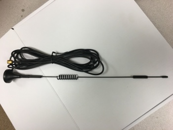
====3G/4G Antenna==== | ====3G/4G Antenna==== | ||
Revision as of 17:50, 14 August 2017
Stonkam D8 Installation Guide
Packaging
All components for a specific individual vehicle will be in one box. This way the DVR will be set up for the exact vehicle and configuration.
System Components
Idrive D8 DVR
- DVR with SSD & SIM card installed and configured for specific vehicle
- Security Box
- Power Cable and Fuse
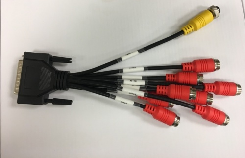
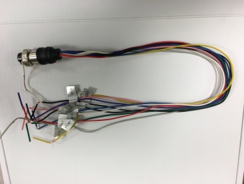
- 44Pin Camera Breakout Cable
- Dual 3G/GPS Antenna
- Keys
- Remote Control (Batteries Installed)
Camera Types
- IDRDVRWPRCAMDIN - Waterproof Rear View CAM
- IDRDVRD4CAM1 - Standard CCD Dome Cam (No Audio)
- IDR8165CAM - 155 degree view
Video Splitter (4 channels)
For use in Cranes only to route the video from the existing 4 camera monitor system to the DVR.
- Video Splitter (4 Channels)
- Four 3 meter cables (from Splitter to DVR)
Monitor
One Per Location
Connections
Before Installations on cranes verify that the existing installed equipment is functioning. Idrive is not responsible for the 4 installed cameras or monitor system on cranes.
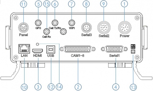
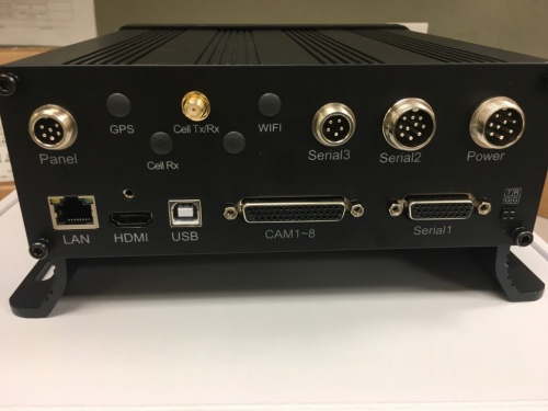
Back Panel Diagram
| Back Panel Connections | |
|---|---|
| 1) Power input (12-32V) | 9) Panic button, external GPS module connector |
| 2) Camera cable input | 10) Ethernet(RJ45) |
| 3) HDMI output | 11) 6pin CVBS video monitor output |
| 4) Alarm input/output | 12) USB 2.0 input |
| 5) GPS Connector | 13) debug |
| 6) Cellular Connector, TX/RX | 14) HDMI cable fixing hole |
| 7) Wifi Connector | 15) Cellular Diversity Connector, Rx |
| 8) Can input/output, External temp.sensor input |
Change Picture when we get the model with the GPS
Power
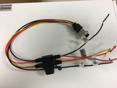
Power Cable
- *Red +12volts
- *Black GROUND
- *Yellow Ignition
Pin 1 : VCC
Pin 2 : VCC
Pin 3 : IGN
Pin 4 : NC
Pin 5 : NC
Pin 6 : GND
Pin 7 : GND
Pin 8 : NC
Pin 9 : NC
Fuses are 5 AMP
Power Connections
Cameras
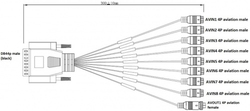
44 Pin Camera Cable
Camera Connections
| Camera Connections | Cam#/Type/Cable | ||
|---|---|---|---|
| Connector | Side Loader | Chassis Handler | Crane |
| AVIN1 | #1 /Dome/ 5m | #1 /Dome/ 5m | #1/Dome/5m |
| AVIN2 | #2 /WP/ 10m | #2 /WP/5m or 10m? | #2/WP/10m |
| AVIN3 | #3 /WP/ 10m | #3 /WP/ 10m | #3/WP/10m |
| AVIN4 | #4 /WP/ 10m | #4 /WP/ 10m | #4/WP Wide Angle/65m |
| AVIN5 | N/A | N/A | #5 /Splitter CH1/ 3m |
| AVIN6 | N/A | N/A | #6 /Splitter CH2/ 3m |
| AVIN7 | N/A | N/A | #7 /Splitter CH3/ 3m |
| AVIN8 | N/A | N/A | #8 /Splitter CH4/ 3m |
Mounting Locations
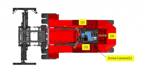
Side loader Camera Locations & Mounting
- #1 Dome Cam mounted above and to the Left of driver On screen name: CAB
- #2 Waterproof Cam On screen name: R-Front
- #3 Waterproof Cam On screen name: L-Front
- #4 Waterproof Cam On screen name: Rear
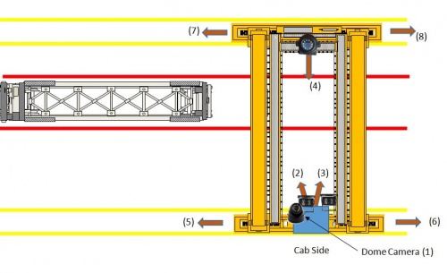
Crane Camera Locations & Mounting
- #1 Dome Cam mounted above and to the Left of driver On screen name: CAB
- #2 Waterproof Cam On screen name: L-Front
- #3 Waterproof Cam On screen name: R-Front
- #4 8165 Cam On screen name: Far-Side
- #5 - #8 Existing installed cameras On screen name? (8 letters max) suggest:????
3G/4G Antenna
Mounting location instructions here
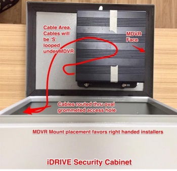
Anti-Tamper Security Box
Install it - real pictures are coming
Extra Cables Not used
10 Pin Alarm, External GPS Cable
5 Pin Can I/O, Temp Sensor Cable
26 Pin DB Cable (RS232 etc)
Video Monitors
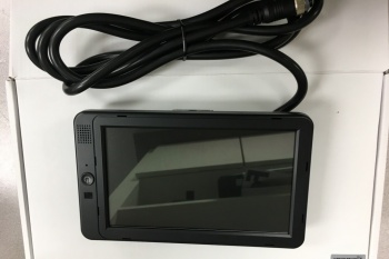
7" Monitor
Configuration is done at Idrive prior to shipment. We supply a standard regular monitor for customer locations to be used for video playback.
Plug into Video Out (Yellow 4 Pin Connector) on the 44Pin Cameras cable using the Male to Male adaptor.
Touch Screen Monitor
Model HD297 touch screen Monitor has two video inputs, HDMI & 6 Pin Aviation - use the Monitor's Remote (Not DVR Remote) to change the input between HDMI and 6 Pin
① HD293 power button, LED red for stand by mode, and green for working mode
② HDMI connector
③ HDMI cable
④ HD293 6pin aviation cable connector, with Power and Video/Audio pin.
HD293
Description HD 10.1"Color monitor
Features used for HD DVR
Resolution 1024 x 600 (RGB)
Maximum Number of Cameras 1
Audio input 1
Audio output (loudspeaker) 1W
HDMI input 1
VGA input /
Functional Test and Sign Off
- Connect Monitor to system
- Power On system
- Verify video for all channels is working (4 channels for loaders, 8 channels for cranes)
- Verify the cameras are upright and pointed at the correct location
- Contact Idrive Support 805-273-4196 to confirm the DVR is registered on the server
- Verify GPS
- Verify Cellular conection
- Verify Video Loss Alarm
- Disconnect one camera to verify Alarms emails are working. Reconnect camera
- Turn Keys and Remote control over to terminal manager
- Manager sign off sheet for installation complete We need to create one.
