Difference between revisions of "RMA Processing Policy and Procedures"
| Line 114: | Line 114: | ||
<br/><br/><br/><br/><br/><br/><br/><br/><br/><br/><br/><br/><br/><br/> | <br/><br/><br/><br/><br/><br/><br/><br/><br/><br/><br/><br/><br/><br/> | ||
| − | ===Reprogram the | + | ===Reprogram the Main Board=== |
| + | |||
| + | [[File:ft2rmamode.jpg|thumb|600px|]] | ||
'''1)''' Remove the screw from the back of the case and open the camera | '''1)''' Remove the screw from the back of the case and open the camera | ||
| Line 126: | Line 128: | ||
::-<span style="color: red"> More stuff? | ::-<span style="color: red"> More stuff? | ||
| − | '''3)''' Place the board in the DUT Holder and Plug the Power and | + | '''3)''' Place the board in the DUT Holder and Plug the Power, HDMI and Wifi cables to the camera <span style="color: red"> Verify this! |
'''4)''' Remove the SD Card and replace it with the Firmware SD Card | '''4)''' Remove the SD Card and replace it with the Firmware SD Card | ||
| Line 134: | Line 136: | ||
::- Reformat the SD card using Long Format | ::- Reformat the SD card using Long Format | ||
| − | ''' | + | '''5)''' Launch Factory Tools V2 and select RMA mode (password idrive2#rma) |
| + | |||
| + | '''6)''' Enter the Serial Number for the camera and press return | ||
| + | |||
| + | ::- For V5 Cameras this will be the MAC address from the label on the back of the case | ||
| + | |||
| + | ::- For V7 Cameras this will be from the Bar Code Label on the SD Card Socket | ||
| + | |||
| + | '''7)''' Install Boot Loader , Kernel, FileSystem , Device Config | ||
| + | |||
| + | ::-Boot Loader in from the HDMI Cable | ||
| + | |||
| + | ::- Kernel and File System are from the SD card | ||
| + | |||
| + | ::-Device config is from the Admin Center via the Wifi | ||
| − | + | ::- Each step registers in the Admin Center. Not internet makes all steps fail. | |
| + | <br\><br\> | ||
===Typical Issue resolution=== | ===Typical Issue resolution=== | ||
Revision as of 22:39, 2 July 2013
RMA Verification and Approval
When a customer reports an issue with a device either by email, phone or ticket system, customer support should verify that there is truly an issue.
1. Verify that there is a problem
2. Once the problem has been verified, Determine if the device is in or out of the warranty period and inform the customer if there definitely will be charges.
- -In Warranty there is no charge for repair of manufacturing defects
- -In Warranty non manufacturing defects there will be charges
- -Out of Warranty there will be charges for repairs
3. Generate and Issue an RMA number so that the device that should be written on the outside of the package.
- -An RMA number consists of the last 6 characters of the serial number followed by the date (ex. 1a2b3c-ddmmyy) If there is more than one device to be returned select any one serial numbers to generate the RMA number and it is applied to all devices.
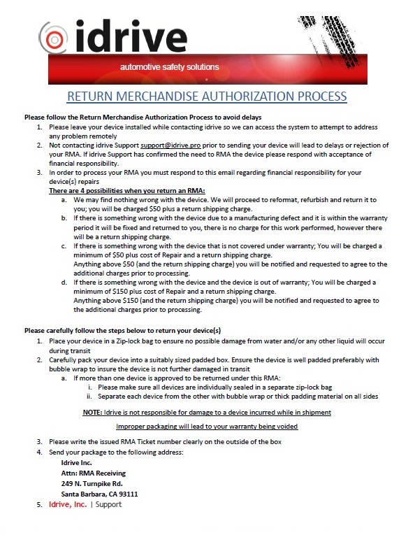
4. Email a copy of the "Complete RMA Process" document to the customer and copy support@idriveglobal.com so the entire team knows what is going on. The document contains
- -Proper Packing information
- -Shipping Address
- -Financial Responsibility
- -information regarding possible plans of action and outcomes for the RMA
RMA Receiving
1) Verify package contents and condition.
- -shipping damage? If so document it with a picture
- - Improper packaging of individual device(s)? If so document it with a picture
- -Correct number of devices?
- -Correct device(s)
2) In the RMA log, record the date the package was received
Where is this log?
3) In admin center, change status of device to “In Factory-not repaired”.
- -Support>Devices enter serial number and click Search
- - Click in the "RMA" field to open the RMA Form
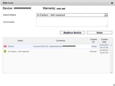
- -Select "IN Factory- Not Repaired" from the pull-down menu. Add any applicable comments.
- -Click Save
RMA Processing
Visual Inspection:
- - Verify condition of plastics/H-bracket
- - Any damage to the Lenses?
- - Any damage or missing pieces to the GPS Puck?
Verification of reported problem
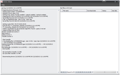
1) Launch Factory Tools V2 and Power on the Access Point
- -Select "Idrive Development Mode" and click on "Event Test - Transfer and play"
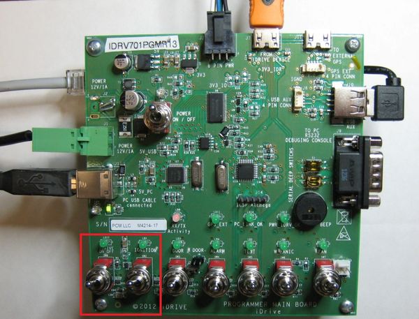
2) Plug the power cable from the V7 Programmer into the camera.
3) Turn the "Idrive ON/OFF switch ON and the Ignition switch ON
- - Does the camera boot up? (normal LED behavior)
- - Do You observer the reported bad behavior from the customer?
4.) Turn the Ignition switch off.
- - Does the device make contact by Wifi?
- - Does it start downloading?
- - Are there events to save on the SD card? if so then...
Reprogram the Main Board
1) Remove the screw from the back of the case and open the camera
2) Remove the Main Board from the camera case
- - Note any observable damage, (Burned parts, Dust, signs of Liquid)
- - Verify the lenses are fixed
- - More stuff?
3) Place the board in the DUT Holder and Plug the Power, HDMI and Wifi cables to the camera Verify this!
4) Remove the SD Card and replace it with the Firmware SD Card
- - Check the SD card you removed and see it there are files to be saved.
- - Reformat the SD card using Long Format
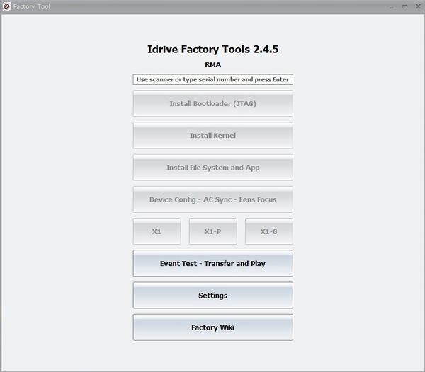
5) Launch Factory Tools V2 and select RMA mode (password idrive2#rma)
6) Enter the Serial Number for the camera and press return
- - For V5 Cameras this will be the MAC address from the label on the back of the case
- - For V7 Cameras this will be from the Bar Code Label on the SD Card Socket
7) Install Boot Loader , Kernel, FileSystem , Device Config
- -Boot Loader in from the HDMI Cable
- - Kernel and File System are from the SD card
- -Device config is from the Admin Center via the Wifi
- - Each step registers in the Admin Center. Not internet makes all steps fail.
<br\><br\>
Typical Issue resolution
- if boot up does not proceed to green/green (stuck red/green) there is likely an issue with the wifi
- if LED boot up cycles constantly (amber/redgreen/redamber/red) the SD card is likely at fault and should be reformatted/replaced
- if improper LED behavior is observed (flickering or unusual LED color) or if there is no LED behavior (no power) there is likely a motherboard issue and it should be replaced
3) Once booted up (green/green) shut off power to push the X1 to connect to wifi
- if the LEDs remain green/flashing amber the wifi is not connecting to the AP. Verify the wireless clients on the router (192.168.0.1) to ensure that it is indeed the wifi at fault
- if the camera connects to the AP but with an incorrect MAC ID, there is an issue with the wifi module and it will need to be replaced.
3) Unplug the camera and turn off power to the test board
2) Open X1 case and verify condition of motherboard (lenses fixed in place)
3) Check the wireless bracket for signs of overheating or melting
- If melting of the bracket is seen, replace bracket
- If an older style antenna is being used, replace with newer antenna
4) Remove internal battery (if present)
5) Apply ziptie to GPS cable for stress relief
6) Neatly wrap GPS cable and tie with ziptie
7) Apply double-sided tape to GPS pod and H-bracket (if included)
Firmware Loading and Image/GPS Test
1) Insert the test SD card with the filesystem and firmware files into the device
1) Plug the X1 into the power cable and the 50-pin adapter cable
2) Turn on power to the test fixture
3) Enter serial number for the device into the factory tool and press enter Note! for V7 main boards the serial number is the barcode lable on the board and NOT the Wifi MAC address
4) Click install bootloader. Click start installation, successful installation indicated by green icon in bottom left of the screen
5) exit the bootloader
6) Install kernel. Click start installation, successful installation indicated by green icon in bottom left of screen
7) Install filesystem. Click start installation, successful installation indicated by green icon in bottom left of screen
8) Click device config. Click start installation
- V7 boards can utilize the netwrok attached to the fixture - V5 boards must be attached to a wifi module
5) Open Reglaj program and select “front camera” tab as starting point
6) Turn on power to the board, flip the test switch and then turn on ignition
-if board does not boot up and enter video mode after some time, turn of power and check seating of serial adapter on the X1 board
7) Upon entering video mode, verify the quality of image for both front and back cameras by navigating the tabs
- make lens adjustments where needed
8) Switch to the “debug events” tab to verify GPS functionality
- should get a green “OK” next to the GPS title as well as a dynamic feed of information at the bottom of the screen. If not, the GPS likely needs replacement
Testing
1) Plug the X1 back into the second test station and turn on power
2) Allow the X1 the boot up (green/green) before turning off ignition to connect with AP
- if the camera connects properly the serial will be saved to the server (displayed in Factory Device Tool)
- if the camera does not connect or connects with an incorrect serial number, the wifi will need to be replaced (see Wifi Replacement section)
3) After successful connection, turn ignition back on and allow for proper boot-up
4) Once LEDs are green/green, test each event (door, shock, panic, wireless panic, and alarm) and verify the LED behavior corresponds with a “record” state (green/red)
- if the events do not record successfully or if LED behavior is abnormal, the motherboard will likely need replacement
5) Once all events have been triggered and the LEDs have returned to green/green, shut off ignition to allow for event transfer
-upon transferring, a progress indicator is displayed in the Factory Device Tool
6) Verify the videos in the control center under “New Events” tab
Returning Refurbished Devices to Customer
1. When testing has been completed, unplug the power cable connecting the device to the second test station.
2. Replace the front road case plastic and secure the screw in the back of the camera.
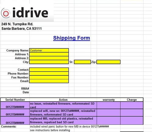
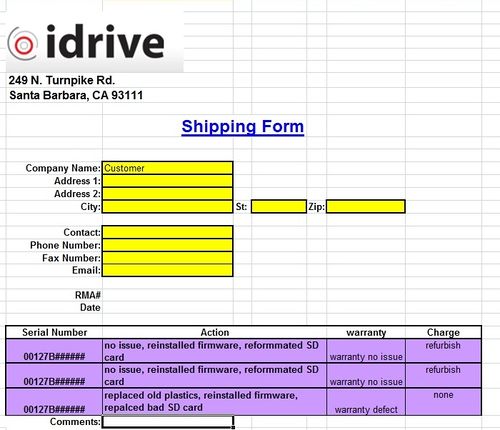
3. Record all actions taken for each camera in the RMA shipping form under the 'action' column (below).
4. If needed, input any comments for the customer into the comments section of the shipping form.
| Item replaced | Action |
|---|---|
| wifi module | place a sticker with the new serial number on the back road case using the label gun. |
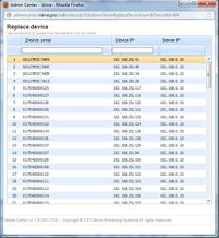
| be sure to replace the original device in admincenter with the new serial number using the "Replace Device" button under the original serial number's RMA status tab (depicted below) | |
| set the status of the old device to 'defect', record the replacement serial number in the comments, and assign it to company: Idrive monitoring sytems, location: Dead or retired devices |
| Item replaced | Action |
|---|---|
| Motherboard | verify whether or not a wired panic button should be included in the returned RMA |
| If the motherboard being replaced was an older version (5.0.1, 5.0.7, or 5.0.9) then a wired panic button should be included with the newly refurbished camera | |
| If the motherboard being replaced was version 5.0.10 or later, verify that the customer already has a wired panic button for the device before shipping. |
Finacial Process
1. In the event that RMA repairs result in charges that need to be paid by the customer, fill out the RMA shipping form accordingly and hold the package until payment has been received. An example shipping form is shown here:
Under the 'warranty' column, record the warranty status of each device individually according to the four categories listed below (In warranty defect, In warranty damaged, Out of Warranty, or In warranty no issue)
2. Under the 'charges' column, list each item that the customer is being charged for, according to the list below.
3. Give a copy of this shipping form to Finance (finance@idriveglobal.com) so that an invoice can be created and sent to the customer
Repair Costs
In Warranty Manufacturing Defect
| Item | Cost |
|---|---|
| Main Board | $0 |
| Wifi | $0 |
| wifi components | $0 |
| GPS cable | $0 |
| GPS puck | $0 |
| plastics | $0 |
| SD card | $0 |
In Warranty Damaged
| Item | Cost |
|---|---|
| reconfigure charge | $50 |
| Main Board | $388 |
| Wifi | $95 |
| wifi components | $25 |
| GPS cable | $25 |
| GPS puck | $75 |
| plastics | $25 |
| SD card | $45 |
Out of Warranty
| Item | Cost |
|---|---|
| reconfigure charge | $150 |
| Main Board | $388 |
| Wifi | $95 |
| wifi components | $25 |
| GPS cable | $25 |
| GPS puck | $75 |
| plastics | $25 |
| SD card | $45 |
In Warranty No issue
| Item | Cost |
|---|---|
| General refurbishment | $50 |
