Manufacturing:X2 Programming Station Documentation
Idrive X2 Programming Stations Documentation
Phase One Programmer
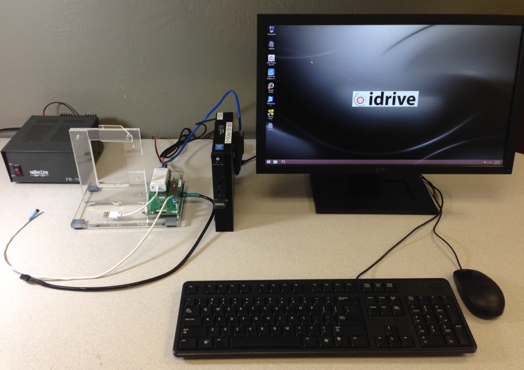
Programming Station Components
| X2 Programming Station Components |
|---|
| Windows 7 or higher Computer with Monitor and speaker(s)(see requirements below) |
| Bar Code Scanner (Optional) |
| Lens Focus Charts |
| Micro SD card reader |
| Idrive X2 Programmer Fixture |
| I/O Loopback Test Adapter |
| DC 12V/1A LINEAR power supply |
| USB type B cable |
| USB to Ethernet adapter |
| Cat5 Cable |
| Power cable for X2 |
| X2 Serial Programming cable |
<br\>
X2 Programming Computer Setup
Computer Hardware Minimum Requirements
- Monitor (needs to support 1600X1200 screen resolution)
- Speaker(s)
- Windows 10 Professional recommended
- 4GB RAM
- 100 GB Hard Disk
- 2 Network Interface adaptors (NICs)
- Keyboard and Mouse
Network Configuration
- Network Connection to the Programming Fixture
- IP address: 192.168.0.10
- Subnet Mask: 255.255.0.0
- Default gateway: Blank
- Network Connection with access to internet
- DHCP or as required by location
<br\>
Computer Software Requirements
- TeamViewer V11 (http://www.teamviewer.com ) - no license. Install TeamViewer - during setup you need to choose the Personal license installation!
- Idrive Factory Tools 3.6.4
- With Windows 8 -Future Technologies USB Driver for X2 Programming Fixture (http://www.ftdichip.com/Drivers/VCP.htm)
- Windows 10 successfully identifies and installs the drivers
- Firefox Web browser (https://www.mozilla.org/en-US/firefox/new/)
Disabling Driver Signature Enforcement In Windows 8 Permanently
Windows 8 only
Step 1. Open the Windows command promt as “Run as Administrator”.
Step 2. Run “bcdedit -set loadoptions DISABLE_INTEGRITY_CHECKS” (without the “”).
Step 3. To finalize the process run “bcdedit -set TESTSIGNING ON” (without the “”).
Step 4. Reboot and you’re done.
This method it leaves a watermark saying you are in test mode until you disable it again.
WARNING: if the procedure is executed remotely, the reboot should be executed with the fallowing command from Run or cmd.exe:
shutdown -r -f -t 0
to avoid hanging up the restart.
X2 Programming Fixture Setup
<br\><br\>
Computer Connections
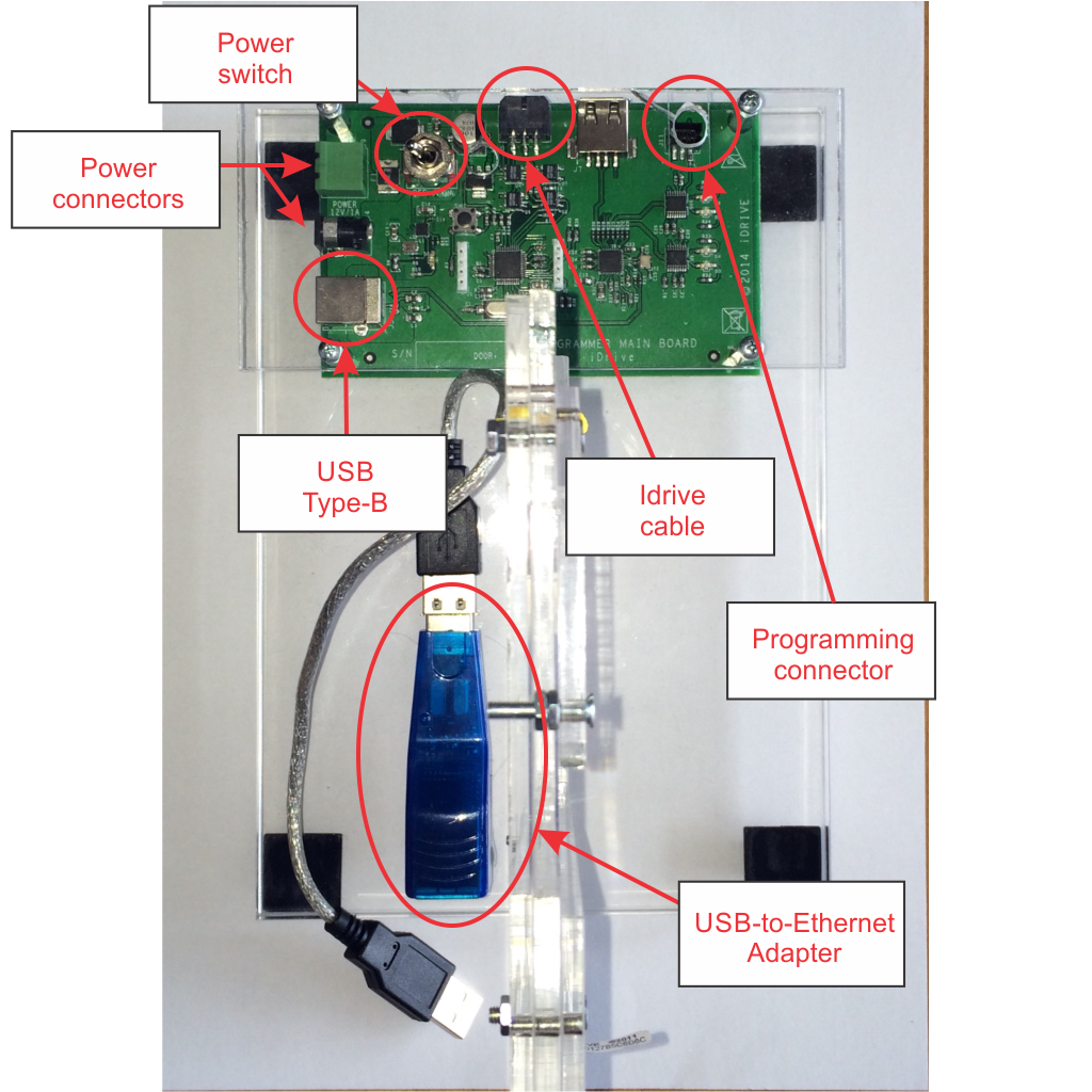
- Connect the 12volt Power Supply to the Power Connector
- Connect the USB cable from Programming computer to USB Type B connector
- Connect the USB-to-Ethernet Adapter to the Programming Computer with a Cat5 (Network) Cable
Idrive Camera Connections
- Connect "Idrive Power Cable" to the Device to be programmed
- Connect the "Programming Connector" to the Device to be programmed
- Connect the USB-to-Ethernet Adapter to the Device to be programmed
<br\><br\><br\><br\>
Turn On the Power switch and leave the programmer on for the batch of boards.(you do not need to turn it off to program the next board)
X2 Programming Fixture Documentation
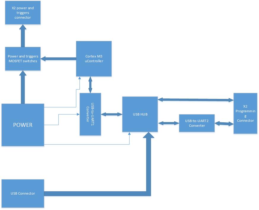
On X2 programming connector there are 2 communication buses present:
- one bus is PC-to-X2 serial connection (using USB to UART converter)(serial one) is used to communicate(send commands receive messages) with U-boot(bootloader) and/or X2's Linux OS (linux console).
- the second bus is PC-to-X2 direct USB connection (USB OTG port of X2 processor)is used only for initial bootloader NAND IC programming or as system recovery in case the bootloader present in NAND IC is corrupted.
When using Factory tool Auto Install or Install Bootloader features, first operation executed by FT is to erase the old bootloader from NAND.
After erasing old one, if X2 processor is not able to "see" the bootloader present in NAND, it enters the system recovery mode by activating it's USB OTG port for a Processor-to-PC direct connection ;this should be confirmed on PC by enumerating a "HID-compilant vendor-defined device" on Device manager (see picture attached).
NOTE: The "HID-compilant vendor-defined device" will appear only when NAND bootloader is missing or corrupted.
From log messages displayed by your Factorytool, it seems that first step (bootloader erase) was performed and the X2 processor USB OTG connection is rejected by PC (please observe "Device Arrival" , "Device Removal" messages present in the log).
In my opinion this is a PC USB problem , for confirmation you can test a known working fixture (for ex: RMA fixture) on this PC.
The fact that shunting the USB-to-serial converter's port does not provide feedback is also indicating PC USB problems.
The only components "involved" in this connection are:
1. Programmer's USB HUB -this is working because you can see/access the USB-to-UART converters.
2. Cable - if cable is bad no HID-compliant device message will ever appear.
3. X2 Processor - known to previously work.
4. PC station
Idrive X2 Secondary/Final Test Station Documentation
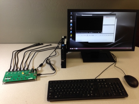
This fixture is used in the factory environment to improve productivity.
Otherwise can use the phase one computer with a simple switch box to turn power and ignition on and off.
Secondary/Final Test Station Components
| X2 Secondary/Final Test Station Components |
|---|
| Windows 7 or higher Computer with Monitor and speaker(s)(see requirements below) |
| USB to Ethernet adapter (Second NIC on Computer) |
| Bar Code Scanner |
| Idrive X6 Test Fixture |
| DC 12V/6A power supply |
| 6 Power cables for X2 |
| Zebra barcode printer |
| USB type B cable (for Printer) |
| 802.11g Wifi access point |
| Cat5 Cable, POE, Shielded FTP Cable |
<br\>
X2 Secondary/Final Test Computer Setup
Computer Hardware Minimum Requirements
- Monitor (needs to support 1600X1200 screen resolution)
- Speaker(s)
- Windows 8.1 Professional recommended
- 1GB RAM
- 100 GB Hard Disk
- 2 Network Interface adaptors (NICs)
- Keyboard and Mouse
Network Configuration
- Network Connection to the Programming Fixture
- IP address: 192.168.0.10
- Subnet Mask: 255.255.0.0
- Default gateway: Blank
- Network Connection with access to internet
- DHCP or as required by location
<br\>
Computer Software Requirements
- TeamViewer V9 (http://www.teamviewer.com ) - personal license. Install TeamViewer - during setup you need to choose the Personal license installation!
- Idrive Factory Tools 3.2.x
- Firefox Web browser (https://www.mozilla.org/en-US/firefox/new/)
X6 Secondary/Final Test Fixture Setup
Computer Connections
- No Direct connection from the X6 Fixture and the PC
- Idrive 802.11g Access point
- Internet connection
Idrive Camera Connections
- Connect "Idrive Power Cable Cable" to the Cameras to be Configured/Tested
<br\>
Turn On the Power switch and leave the programmer on for the batch of boards.
Wireless router Setup
If a wireless router is used with the V7 programmer a small network hub is required to share the idrive programmer NIC on the computer.
- LAN IP address 192.168.0.1
- Network Mask 255.255.0.0
- Default Gateway Blank
- SSID bwifi
- No DHCP
- No DNS
- No WAN settings (not in use)
<br\>


