Manufacturing:X2 Main PCB Board Assembly
Idrive X2 Main Board Assembly
Assemble PCB
| X2 Main Board PCB Assembly Materials |
|---|
| All components as listed in "Idrive X2 REV 1.1 Main Board" Bill of Materials |
| Pre-printed Bar Code Labels with Serial Number |
1. SMT Assembly steps - Use the supplied pick and place information provided by Idrive Inc.
2. Manual Assembly Steps (Through Hole components etc)
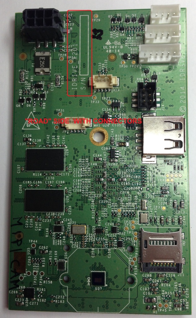
3. Place Barcode label in the S/N box located on the "Road" side of the PCB next to the Power Connector
Top Level X2 Main Board Assembly
| Top Level Main Board Assembly Materials |
|---|
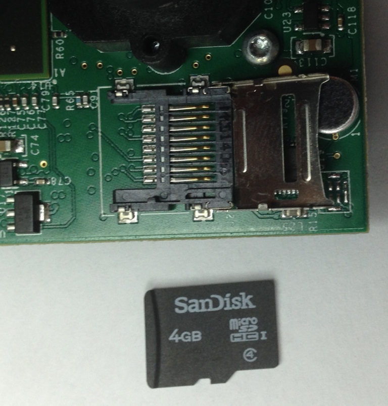
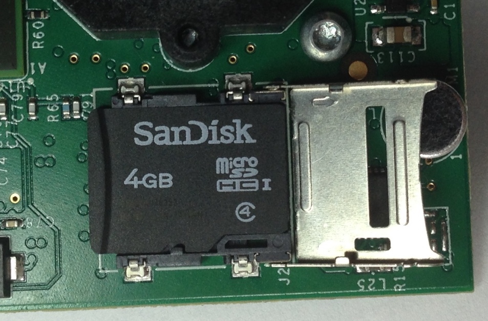
| 4GB Pre-Programmed Micro SD card (Contains OS for camera) |
| 8GB Micro SD card (No pre-programming, used for event storage) |
| 2 Lens Holders (11mm Height) |
| 4 Lens Holder screws (2 for each lens holder) |
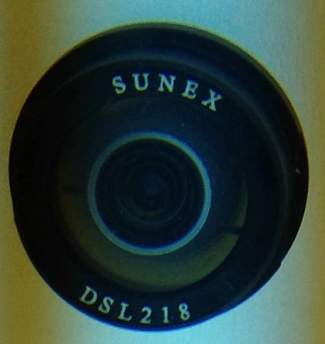
| DSL-218A-670-F2.0 Lens for Road side of the camera (side of the PCB with the power connector)(Lens has Text on it) |
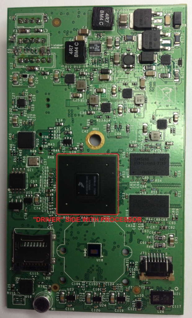
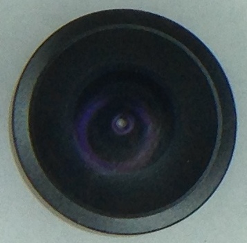
| DSL-180A-NIR-F2.0 Lens for Driver Side of the camera (side of the PCB with the Processor on it)(Lens has NO Text on it) |
| X2 LED board assembly |
| Flat flex Cable |
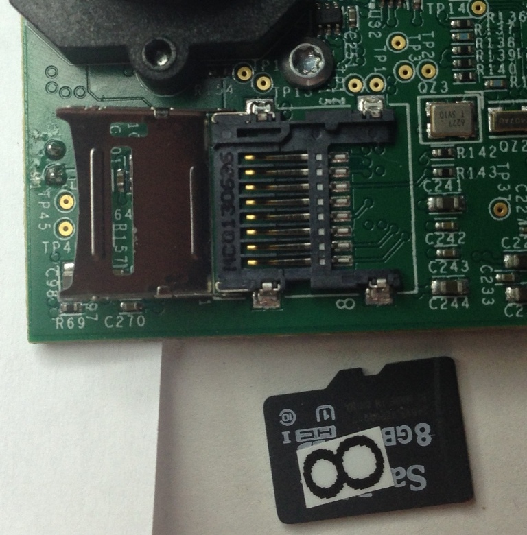
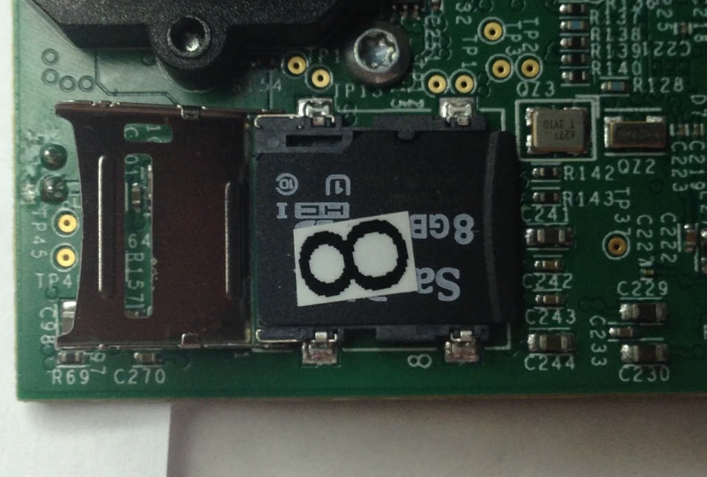
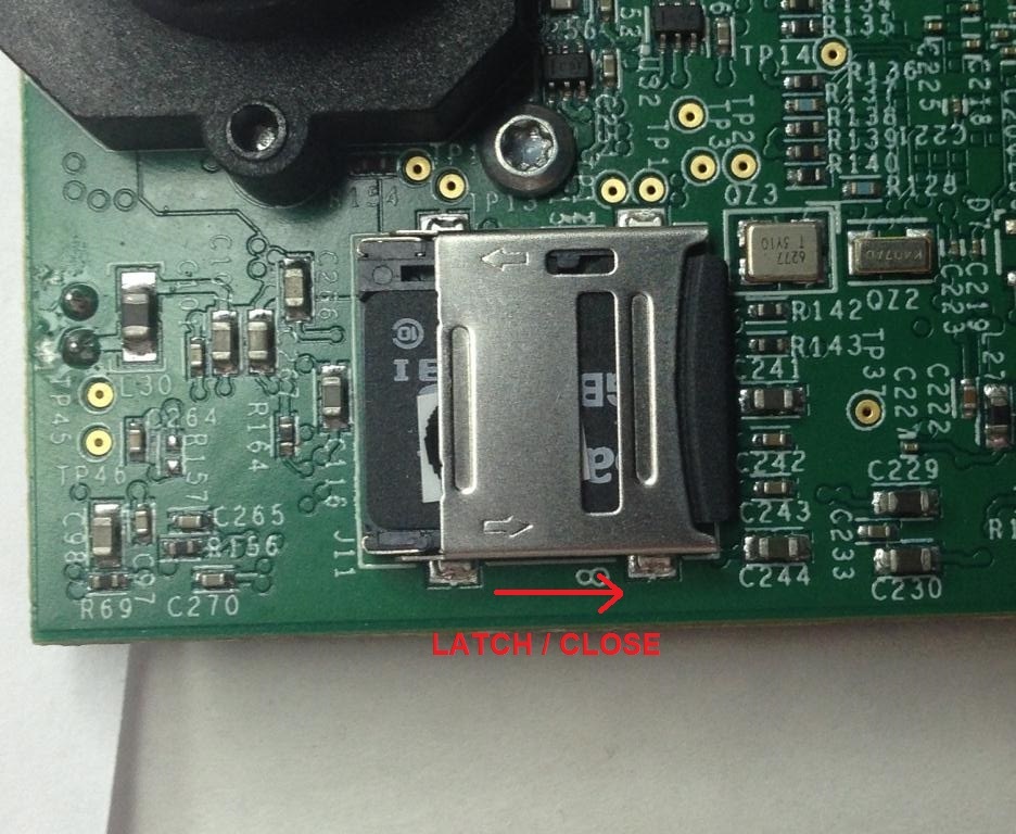
1. Insert the Pre-programmed 4GB Micro SD card into the SD socket on the Driver Side of the Main Board.
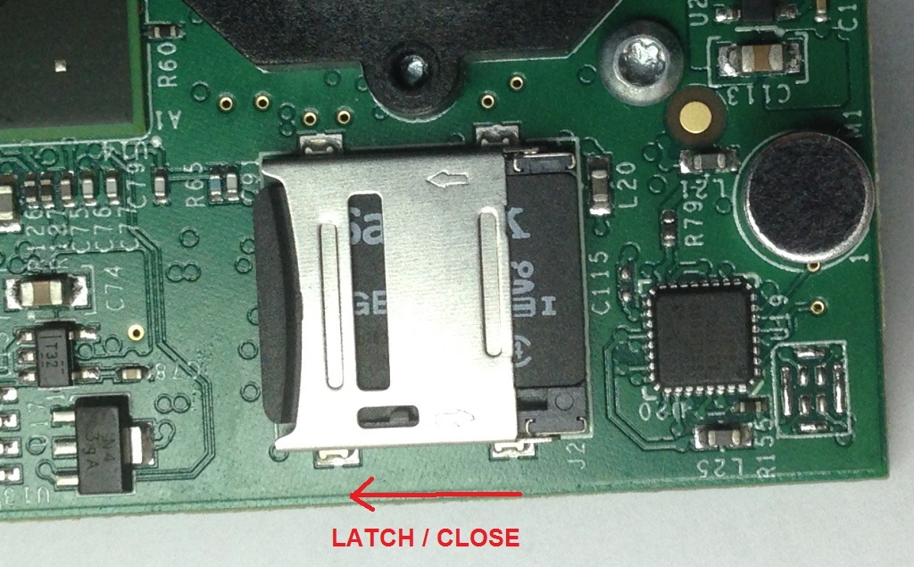
2. Insert the 8GB Micro SD card into the SD socket on the Road Side of the Main Board.
3. Mount of the two Lens Holders to the board
4. Insert the proper lens in the correct side in the Lens Holders(Lenses are glued after programming and focus)
DSL-180A Lens for Driver Side (No markings) ---------------------DSL-218A Lens for Road Side (Note Markings)
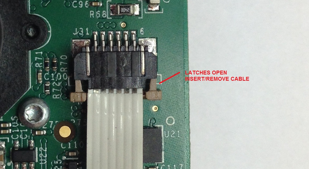
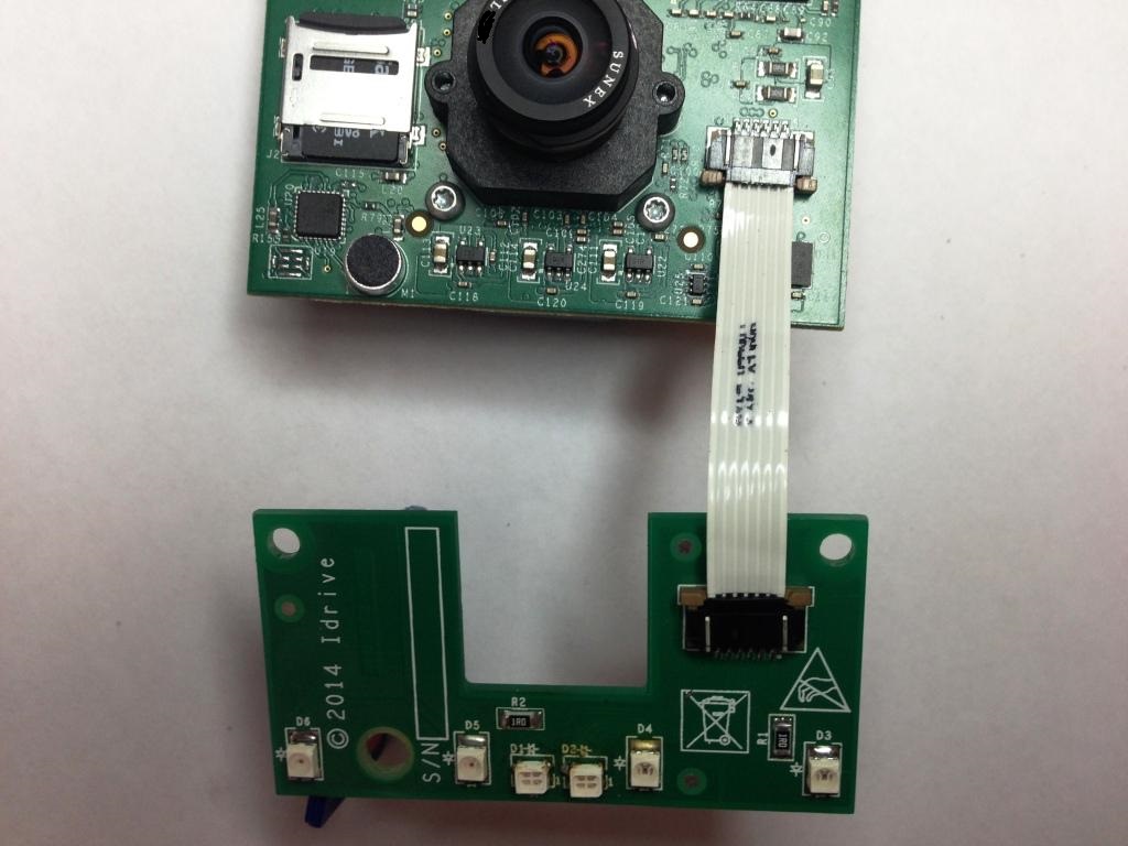
5. Connect the LED Board to the Main Board with the Ribbon Cable
- - Slide cable into the connectors with the contacts up as shown
- - Slide the brown tabs at the sides of the connector to secure cable in place.
The LED Board has been modified and the connector is now on the opposite side of the board.
We will update the picture once we receive the boards
6. Advance the Top Level X2 Main Board PCB assembly to the X2 Programming Station
