Manufacturing:X2 Device Manufacturing and Programming Process
Copyright Information
This document contains proprietary information that is protected by copyright. No part of this document may be photocopied, reproduced, or translated to another language without the prior written consent of Idrive Inc.
About This Document
This proprietary document contains the information necessary to produce an Idrive X2 series camera. This includes all programming, testing, focus of lenses and bar code label.
About Idrive X2 Production Process
The production process for the Idrive X2 cameras has been created with purpose in mind of tracking all work in progress as well as finished goods. This information is sent over the internet to the Idrive AdminCenter website where it is logged and configuration information is obtained for each device. As much of the testing as possible has been automated however certain steps will require human intervention. Wherever possible a bar code reader is used to reduce input errors.
To facilitate this tracking each X2 Main board MUST HAVE a unique serial number assigned to it. Idrive produces the range of serial numbers for each build and allocates them to the assembly vendor when a purchase order is issued. Each serial number must remain unique and track through the production process all the way to a finished camera (which will inherit this serial number) or to scrap of the PCB assembly due to defect. A serial number should NEVER be reused.
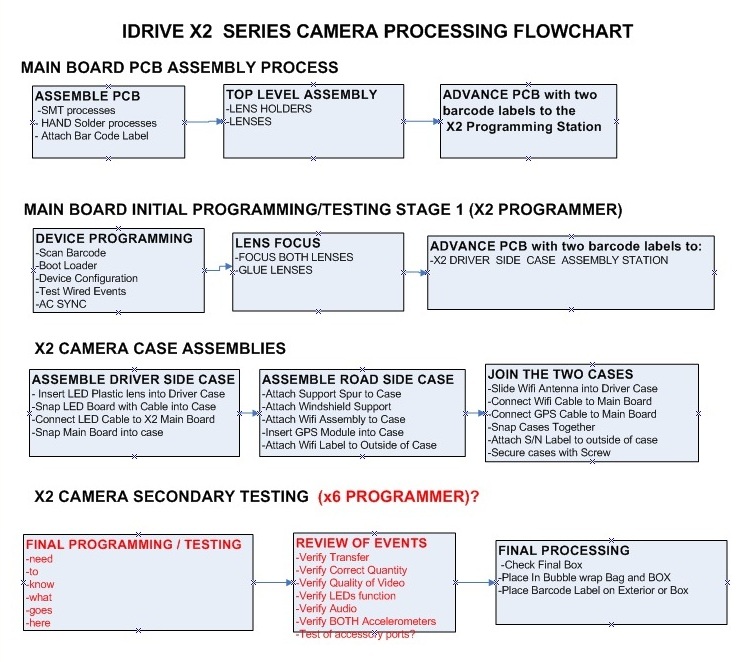
Idrive X2 Camera Processing Overview
Idrive X2 Main Board Assembly
Assemble PCB
| X2 Main Board PCB Assembly Materials |
|---|
| All components as listed in "Idrive X2 REV 1.2 Main Board" Bill of Materials |
| Pre-printed Bar Code Labels with Serial Number |
1. SMT Assembly steps - Use the supplied pick and place information provided by Idrive Inc.
2. Manual Assembly Steps (Through Hole components etc)
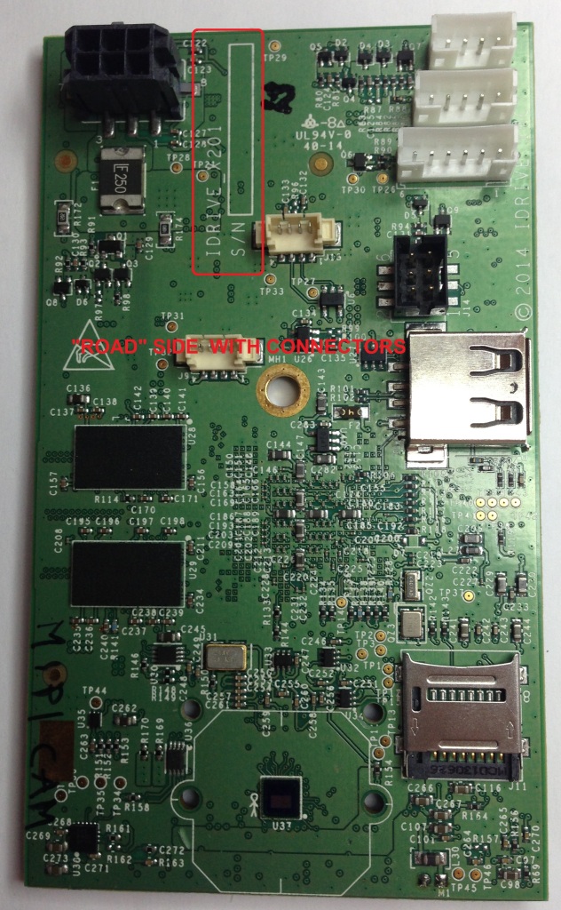
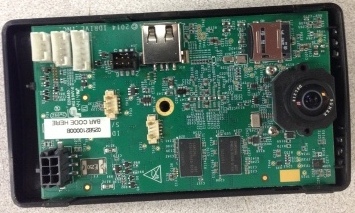
3. Place Barcode label in the S/N box located on the "Road" side of the PCB next to the Power Connector
Top Level X2 Main Board Assembly
| Top Level Main Board Assembly Materials |
|---|
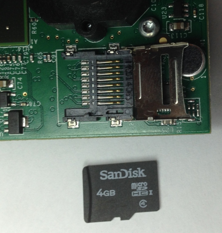
| 4GB Pre-Programmed Micro SD card (Contains OS for camera) |
| 32GB Micro SD card (No pre-programming, used for event storage) |
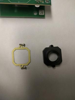
| 2 Metal Lens Holders (11mm Height) |
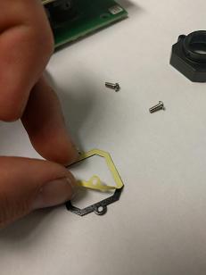
| 2 Lens Holder Gaskets |
| 4 Lens Holder screws (2 for each lens holder) |
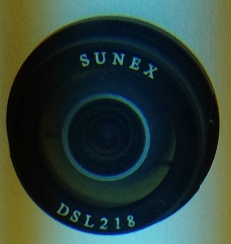
| DSL-218A-670-F2.0 Lens for Road side of the camera (side of the PCB with the power connector)(Lens has Text on it) |
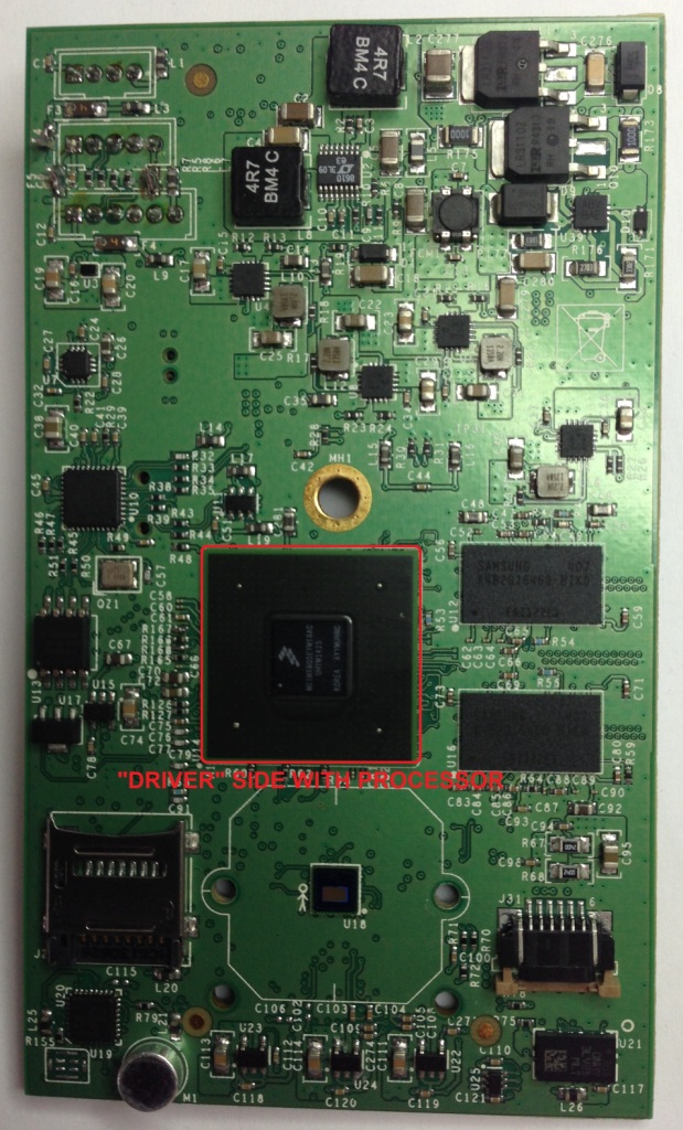
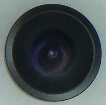
| DSL-180A-NIR-F2.0 Lens for Driver Side of the camera (side of the PCB with the Processor on it)(Lens has NO Text on it) |
| X2 LED board assembly |
| Flat flex Cable |
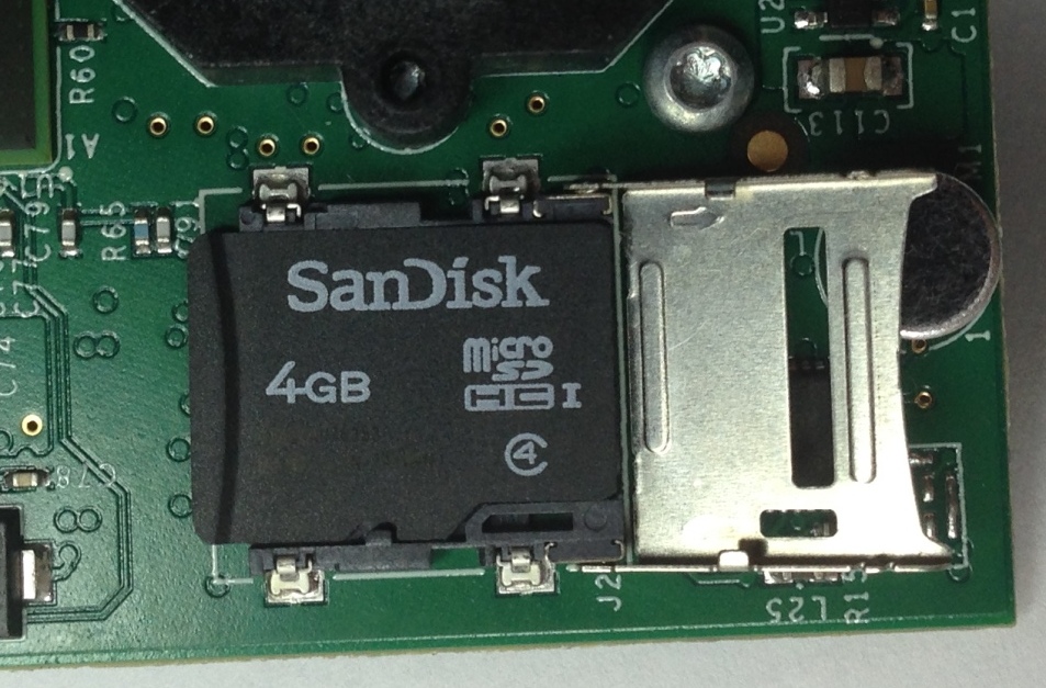
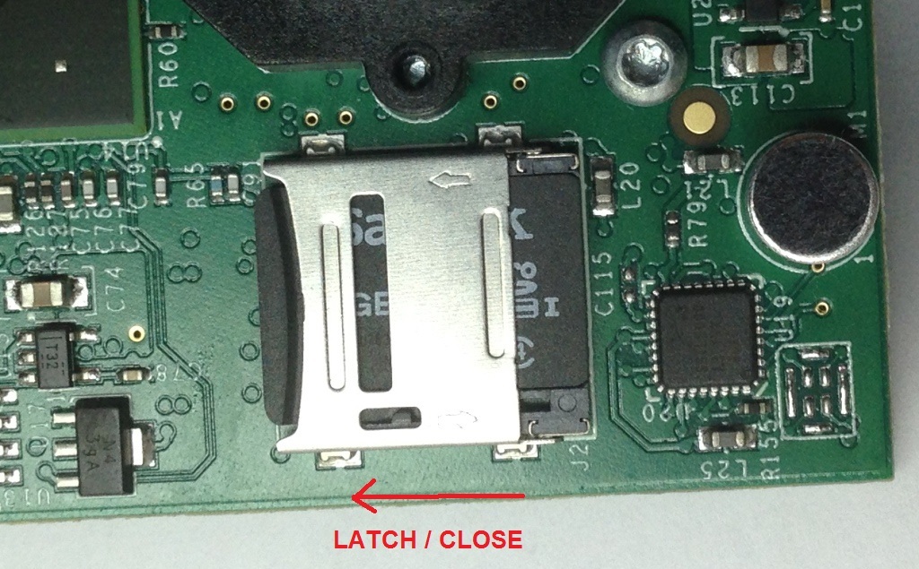
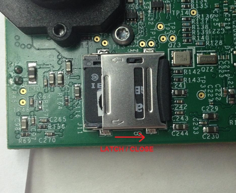
1. Insert the Pre-programmed 4GB Micro SD card into the SD socket on the Driver Side of the Main Board.
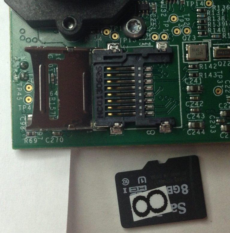
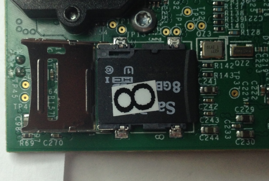
2. Insert the 32GB Micro SD card into the SD socket on the Road Side of the Main Board.
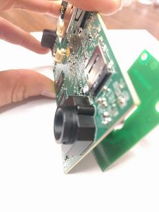
3. Mount two of the Lens Holders to the board
4. Insert the proper lens in the correct side in the Lens Holders(Lenses are glued after programming and focus)
DSL-180A Lens for Driver Side (No markings) ---------------------DSL-218A Lens for Road Side (Note Markings)
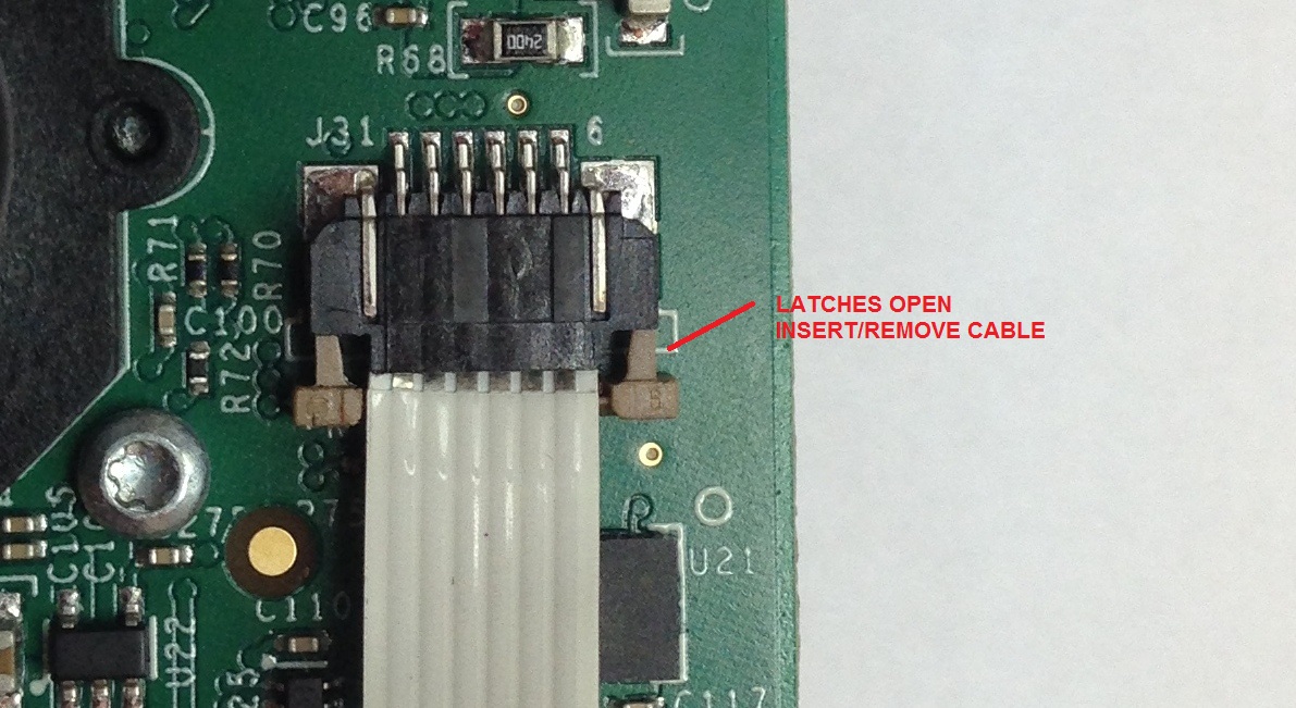
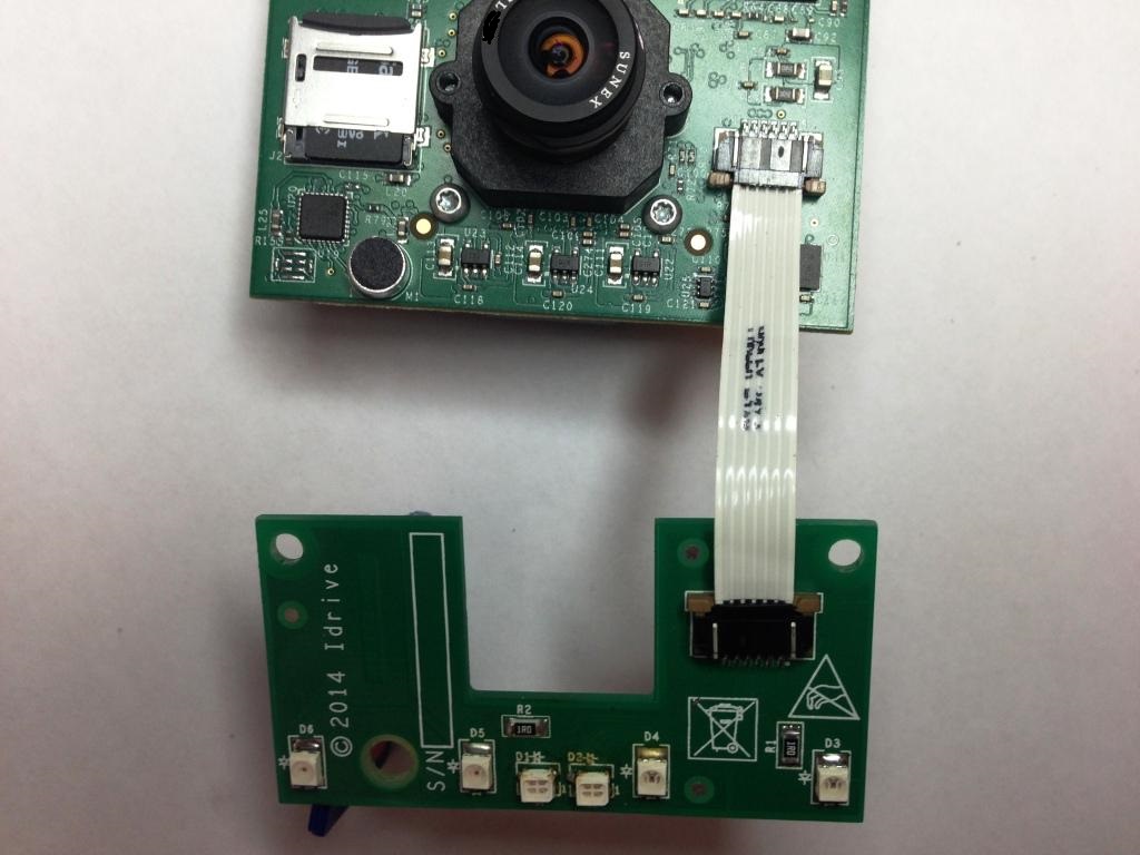
5. Connect the LED Board to the Main Board with the Ribbon Cable
- - Slide cable into the connectors with the contacts up as shown
- - Slide the brown tabs at the sides of the connector to secure cable in place.
The LED Board has been modified and the connector is now on the opposite side of the board.
We will update the picture once we receive the boards
6. Advance the Top Level X2 Main Board PCB assembly to the X2 Programming Station
Idrive X2 Main Board Initial Programming
| Idrive X2 Programming & Lens Focus Materials |
|---|
| Idrive X2 Programming Station |
| I/O Test Loopback Board |
| Idrive Top Level X2 Main Board Assembly |
| Lens focus targets |
| Super Glue (for fixing lenses) (Loctite Control, Extra Time or equivalent) |
Initialize Firmware Programming Station
Setup X2 Main Board
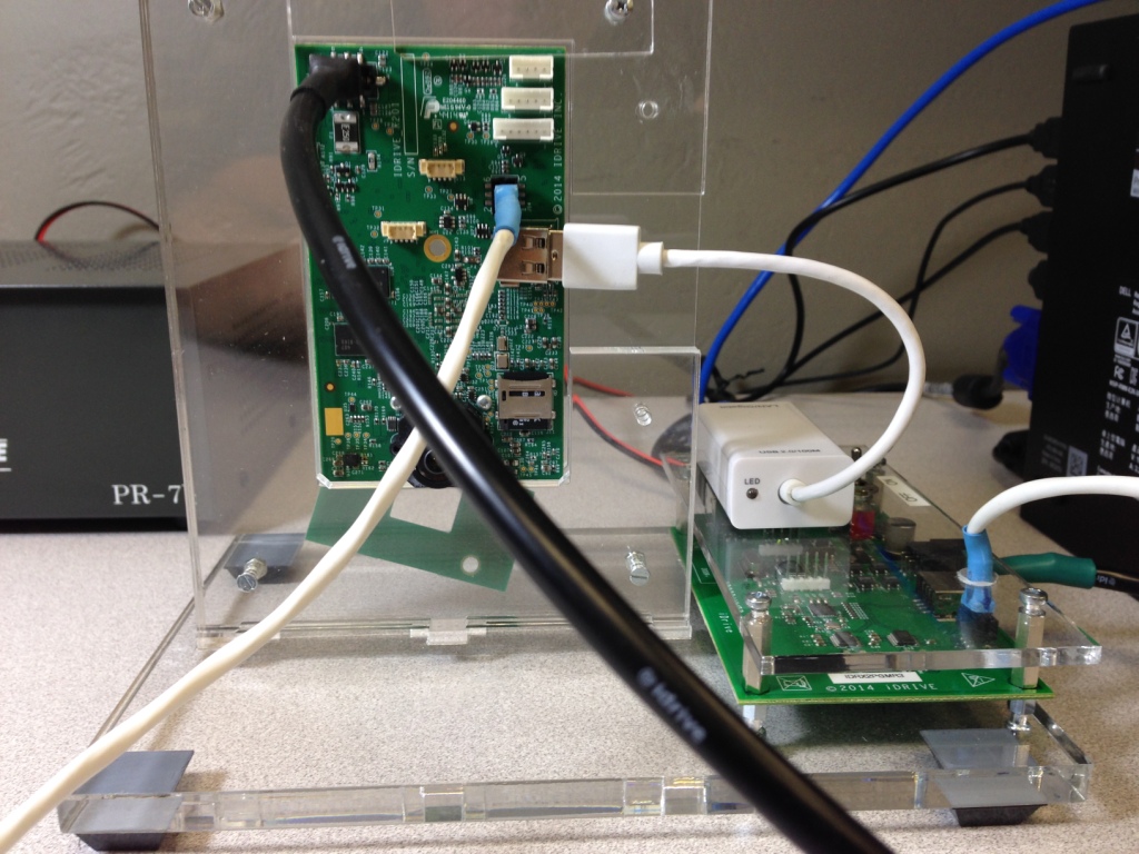
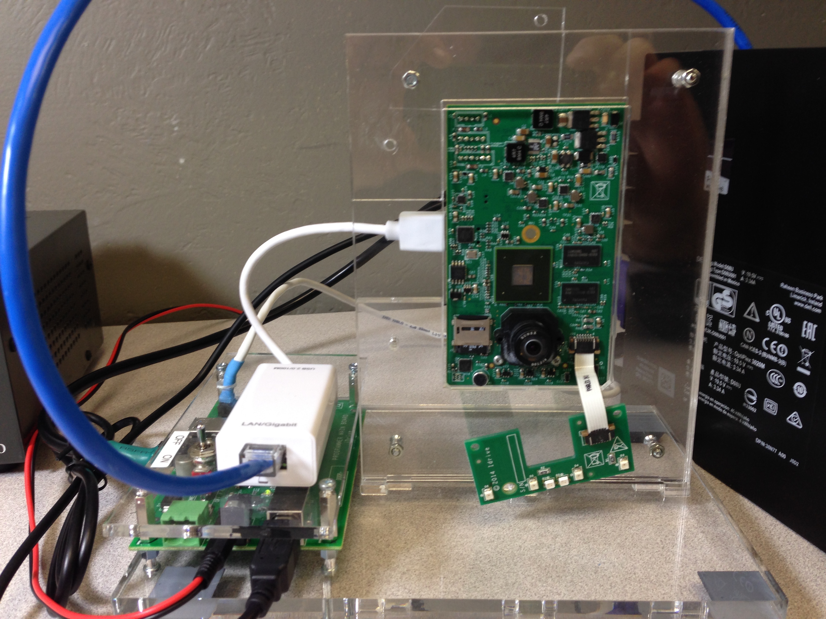
1. Place the Idrive X2 Main board into the Device holding Fixture.
2. Connect the Power cable between the Idrive X2 Main Board and the Programming Fixture.
3. Connect the serial programming cable between the Idrive X2 Main Board and the Programming Fixture. (observe polarity)
4. Connect the USB Network Adapter to the Idrive X2 Main Board.
5. Plug in I/O Test board Into Accessory Connectors
Need a new Picture with I/O board shown
<br\><br\>
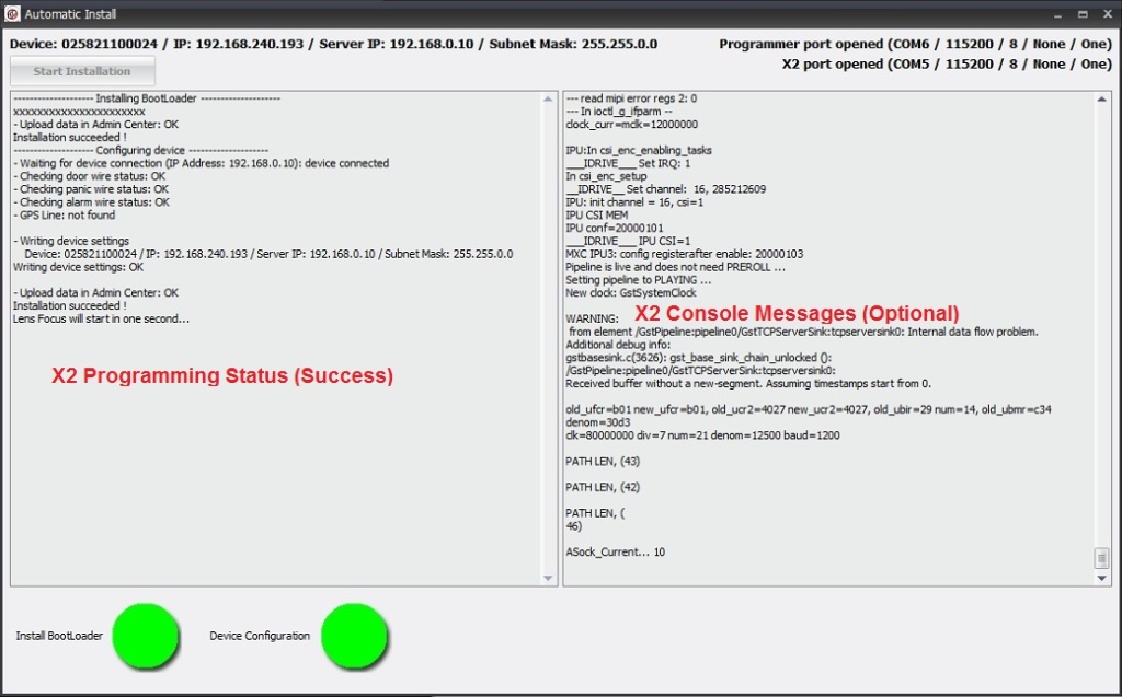
X2 Automatic Install and Configuration
Notes: The Automatic install performs the following:
- installs the boot loader into the X2 board. (The Kernel and filesystem are pre-installed on the 4GB SD card)
- gets device configuration from the Idrive AdminCenter (IP address configuration)
- Tests triggering on the yellow, blue and green wires
- provides lens focus mode so both lenses can be focused and glued
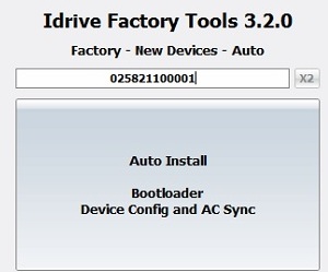
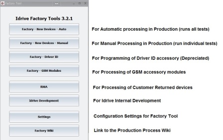
1. Click on the Factory-New Devices-Auto button ![]()
2. Scan the Bar Code label on the device to be programmed and press Enter.
(if no bar code scanner is available type the serial number from the bar code label into the serial number input field )
3. Click on the Auto Install Button and the Automatic Install window will open, Click on Start Installation
- If any of these steps fail the program will stop and give an error. Common errors are:
- Missing or corrupt OS on 4GB SD card
- Missing or corrupt storage SD card
- Serial cable not connected or incorrect polarity
- USB NIC or Internet connection missing
- I/O ports tester board missing
- Any assembly or incorrect component error
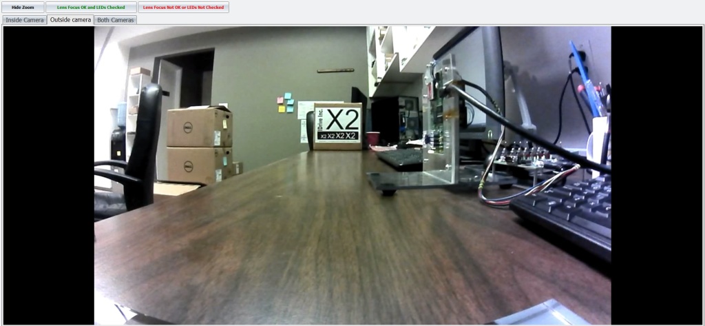
If all steps are successfully completed the program will enter into Lens Focus / LED test mode Mode.
Lens Focusing
1. Select "Inside Camera" Tab and Focus the Driver Side Lens(DSL-180A) (the same side as the Processor).
- The focal length for the inside camera should be ~1.5 meters
2. Select "Outside camera" Tab and Focus the Road Side Lens (DSL-218A) (the same side as Power Connector).
- Focus using the provided Idrive Focus Chart. Distance to chart can be 3,6,9 feet but the farther the better.
- Use zoom mode to ensure accurate focus
4 Verify that the 4 IR LEDs are on (faint red glow in 4 places)
5. If images are focused and clear and the 4 IRLeds are on click on the "Lens Focus OK" button and the focus mode will close. If the image is not clear or any IRLeds are not functioning for some reason click on the "Lens Focus Not OK" the factory tool will exit focus mode so corrective action can be taken.
6. Once focused fix the each lens with a drop of super glue.Test the lenses after several minutes to ensure they have taken the glue and cannot be moved
7. Remove the assembly from the test fixture, remove I/O test board
8. Advance the Main Board Assembly to the Driver Side Case Assembly Station.
Idrive X2 Camera Top Level Assembly
Driver Side Case Assembly
| X2 Drive Side Case Materials |
|---|
| Driver Side Plastic Case |
| LED Plastic Lens |
| X2 Main Board and LED Assembly |
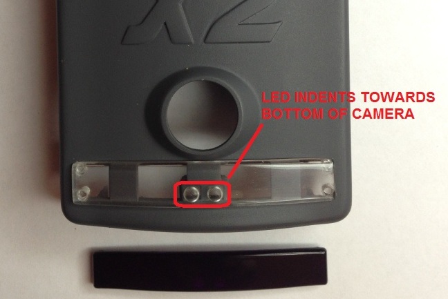
1. Snap the LED Lens into the Driver Side Case
- - Ensure that the two LED indents are towards the bottom of the camera
- - Clear LED lens is shown to enhance the view of indents
- - Actual LED Lens is black/opaque as shown
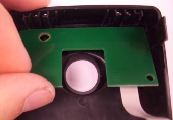
2. Snap the LED Board Assembly into the Driver Side Case as shown
3. Snap the X2 Main board Assembly into the Driver Side Case as shown
Road Side Case Assembly
| X2 Road Side Case Materials |
|---|
| Road Side Plastic case |
| Plastic Support Spur |
| Screw for Support Spur |
| FCC Compliance Label |
| Electronic Module Materials |
|---|
| SparkLan WiFi Module |
| WiFi cable |
| Dual Band WiFi Antenna |
| Screws for WiFi mounting |
| GPS Module Assembly |
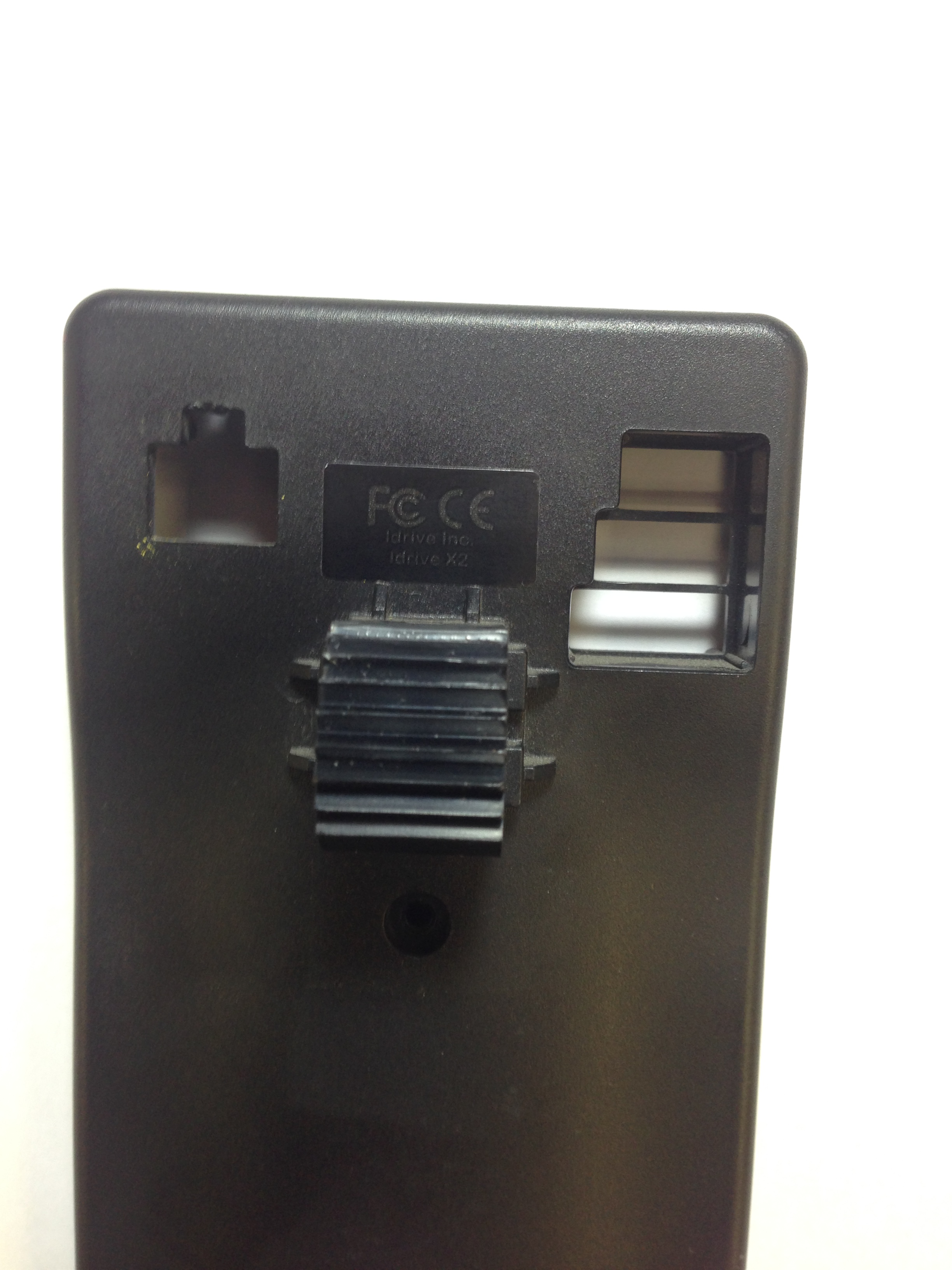
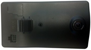
1. Attach Base Support Spur to the Road Side Case with the screw, Place FCC compliance sticker as shown.
- Note correct orientation of Support Spur ("Gear" towards FCC sticker)
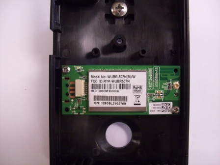
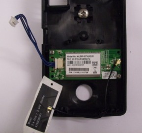
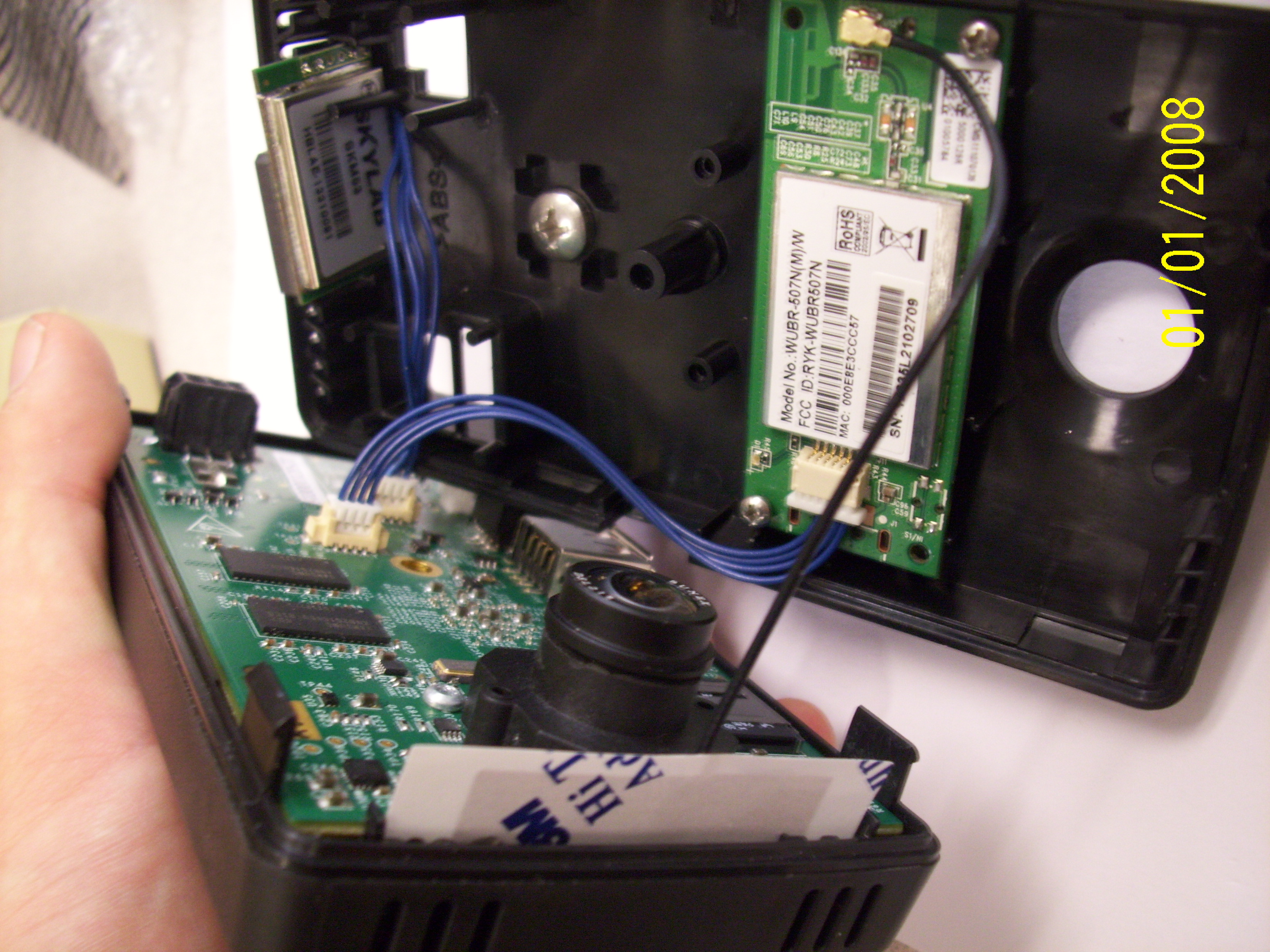
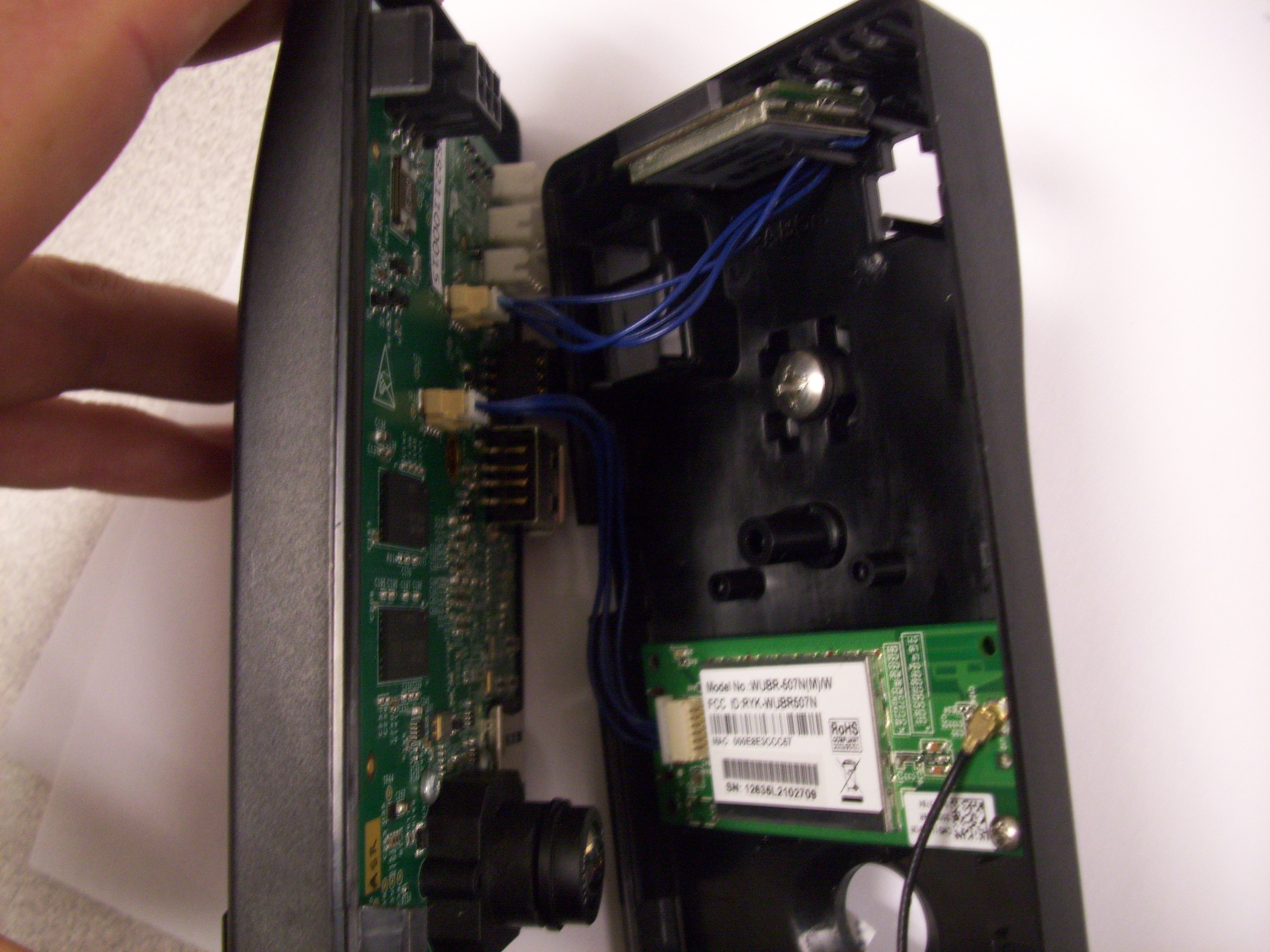
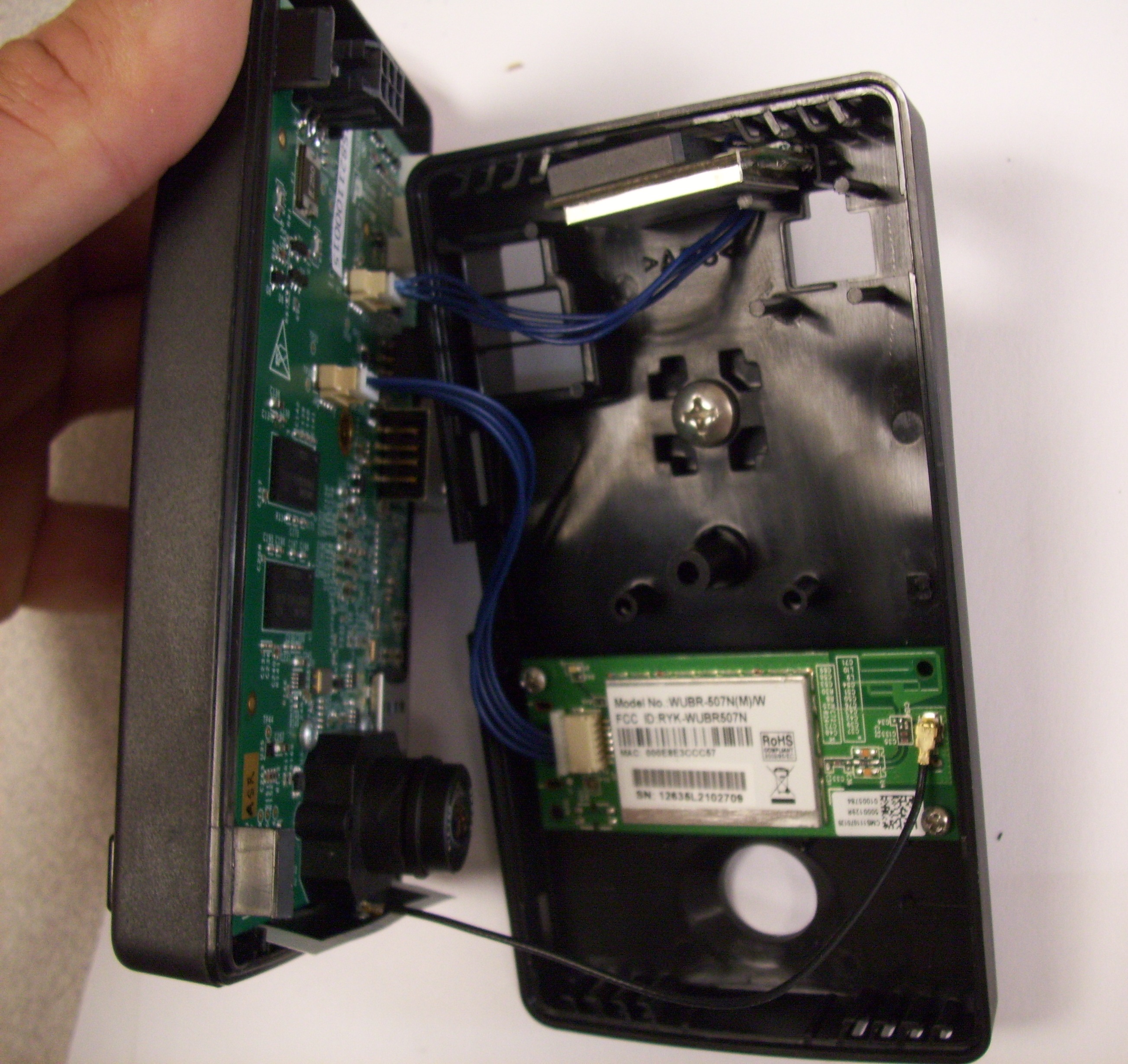
2. Install the Wifi Module with cable and antenna, secure with 2 screws as shown
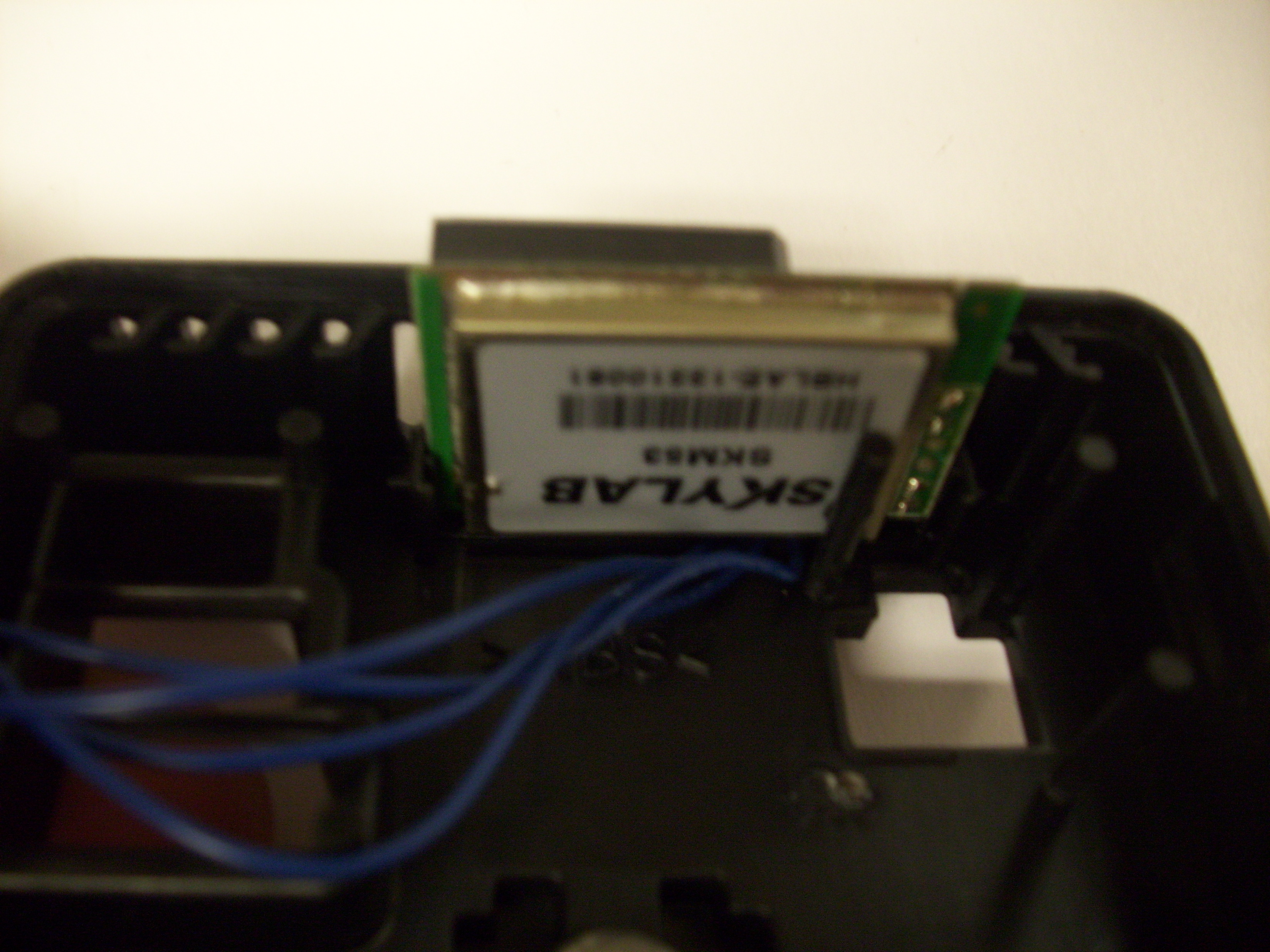
3. Install GPS Module as shown. Ensure the cable is routed properly so as to avoid he power connector opening.
Top Level Camera Assembly
| X2 Top Level Camera Materials |
|---|
| Driver Side Case Assembly |
| Road Side Case Assembly |
| Bar Code Label with Serial Number |
| Plastic Dust Cover for Accessory Connectors |
| Case Screw |
| Wifi Antenna |
1. Connect the GPS and WiFi Cables to the Main Board. Remove the backing tape from the wifi antenna and affix the Antenna on the Driver Side Case as shown.
2. Snap the two halves of the camera together ensuring no cables interfere with or block the Lens, Power Connector, I/O Connectors, USB opening or case screw
3. Install Plastic Dust Cover for Accessory Connectors - move to after final test.
4. Secure the cases to together with the case screw. Do not over torque the screw.
Windshield Support Assembly
| X2 Windshield Support Materials |
|---|
| Plastic Windshield Support |
| Plastic Support Back Plate |
| Screw for Support Back Plate |
| 3M Adhesive Tape |
| Screw for Support attachment to Spur |
| Washer for Support Screw |
| Hex nut for Support Attachment |
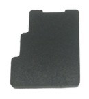
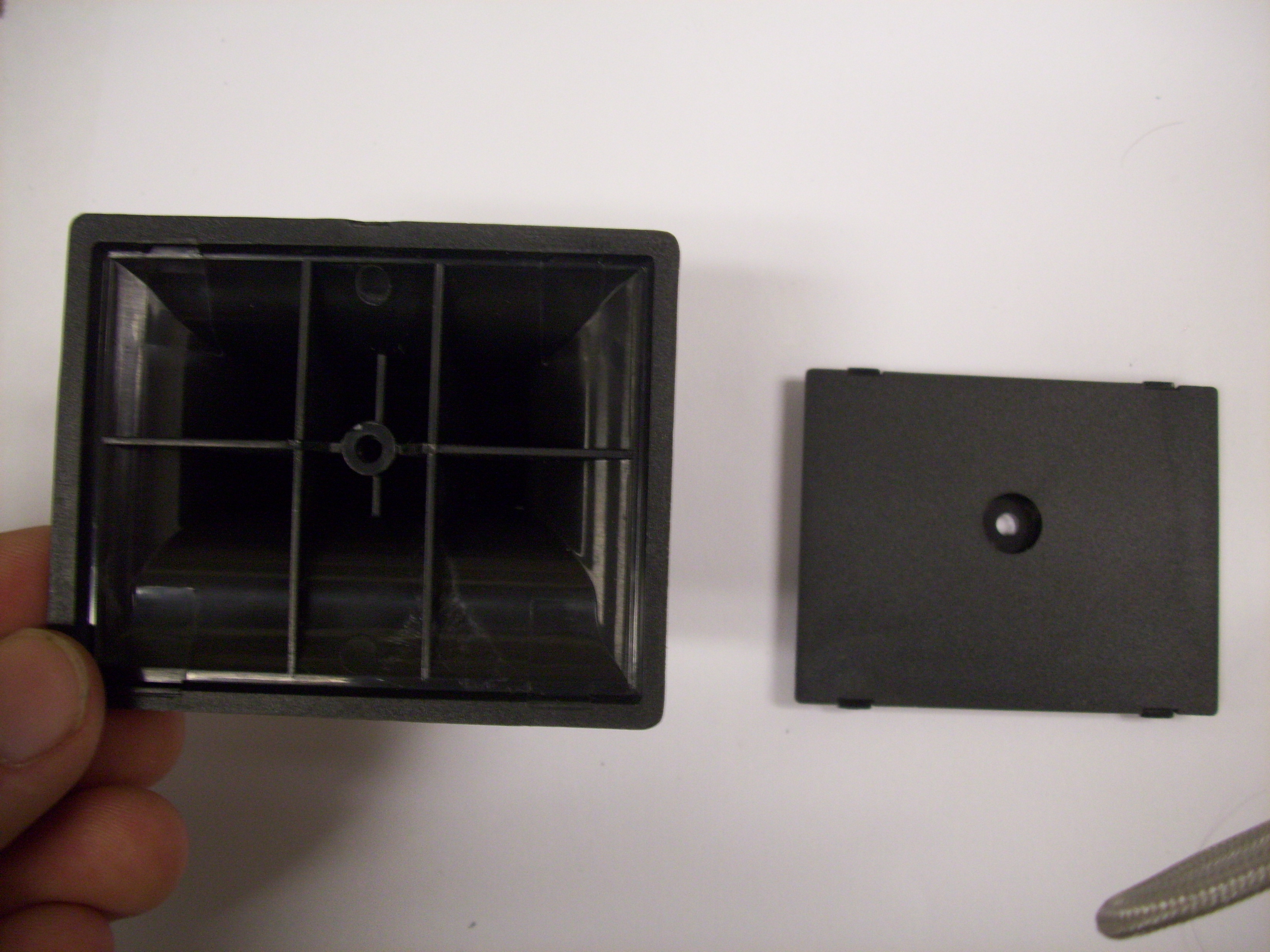
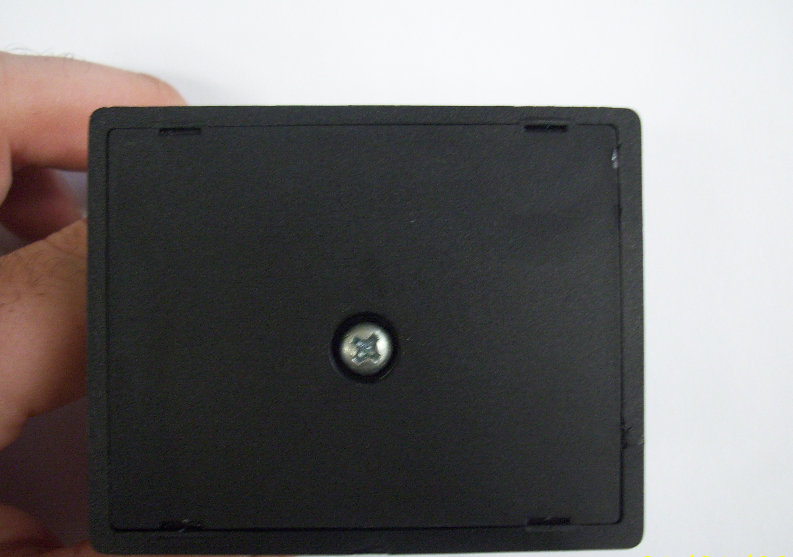
1. Assemble Windshield Support Base Assembly (Windshield support not attached to the camera until after final test or else the power connector would be inaccessible
- Snap plastic back plate into support
- secure with screw
- Apply 3M tape and trim flush with scalpel
Idrive X2 Secondary Testing (Bi-Color LEDS, Accelerometers, IR LEDs, Wifi Transfers, GPS, labeling)
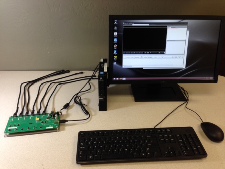
Note:The Idrive X2 programmer may also be used to perform this portion of the programming provided a wireless router is configured and connected to the system. For better throughput and to reduce the number of wireless networks in a factory environment it is recommended that the X6 Fixture be used. Because this document is intended to support production the X6 Fixture process is shown here.
<br\>
Idrive X2 Secondary/Final Test Station Setup
<br\>
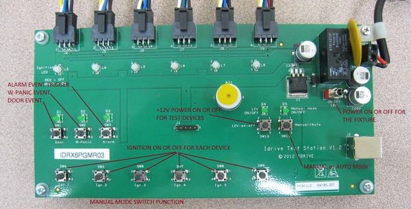
Stage 2 Initialize X6 Fixture
1. Turn on the power toggle switch of the X6 Fixture
2. Connect up to 6 cameras into the x6 programmer using the 6 pin power cables
3. Press any one of the 6 Ignition push buttons to turn on the test cameras
4. When the X2 device's LED are Green/Green the camera is ready to test.
<br\>
Test X2 Internal Accelerometer function
1.Gently shake each camera to trigger a shock event
- Right LED will turn red. Both LEDs green after event finishes recording.
- Alarm/W-Panic and Door events may be triggered by pressing the corresponding push button. (these events are tested in at the first test station so this is optional)
<br\>
Transfer the event(s) to the Test Station
1. Press any one of the 6 Ignition push buttons to initiate transfer of events to the test station.
Verify the Events in Factory Tool
1. Factory Tool verify that each camera downloads
- - Red text is bad (Camera transfered but no shock event was downloaded or failed GPS Data)
- - Black text is good (Camera is pending the label printing process)
- - Green text is good (Passed Accelerometer, GPS and Label application)
- - No text (camera did not download to test station. WiFi failure?)
<br\><br\>
Print Serial Number, Barcode, MAC Address Labels
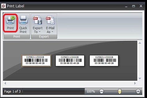
If the transfer(s) and tests are successful Labels for the device can be printed. You must print the labels within 240 seconds* or the tests must be rerun.
- *This timeout length can be changed by Idrive if needed to help with process flow.
Click on "Print(230sec until close)" link to start the print dialog
- When Print is selected the corresponding Camera will flash its LEDs: GREEN/GREEN OFF/OFF RED/RED ... repeat
- You must confirm the label Printed and was attached to the camera before the next Camera can have the label printer.
Click on "Quick Print"
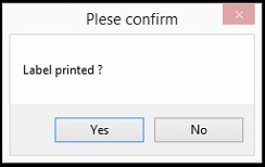
Click On Confirm Label printed if successful.
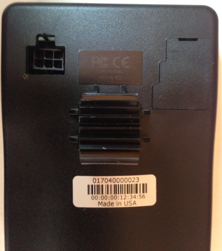
Tear-off the three labels from the printer. Place one Label on the back of the camera covering the case screw as shown. Advance the remaining two labels to Final Assembly/ Packaging.
<br\>
Idrive X2 Final Assembly/Packaging (Windshield support attachment, Final Inspection, Packaging)
| X2 Final Processing Materials |
|---|
| Windshield Support Assembly |
| Screw for attachment of Support to X2 Camera |
| Hex nut for Support Attachment |
| 2 serial number barcode labels |
Attach Windshield support to camera
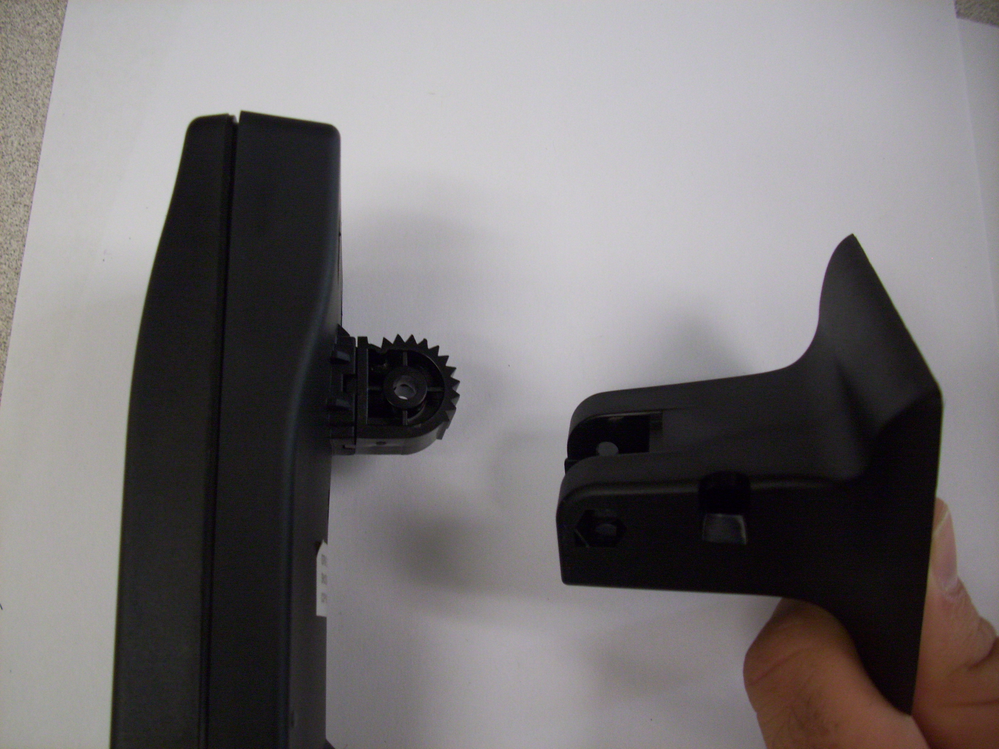
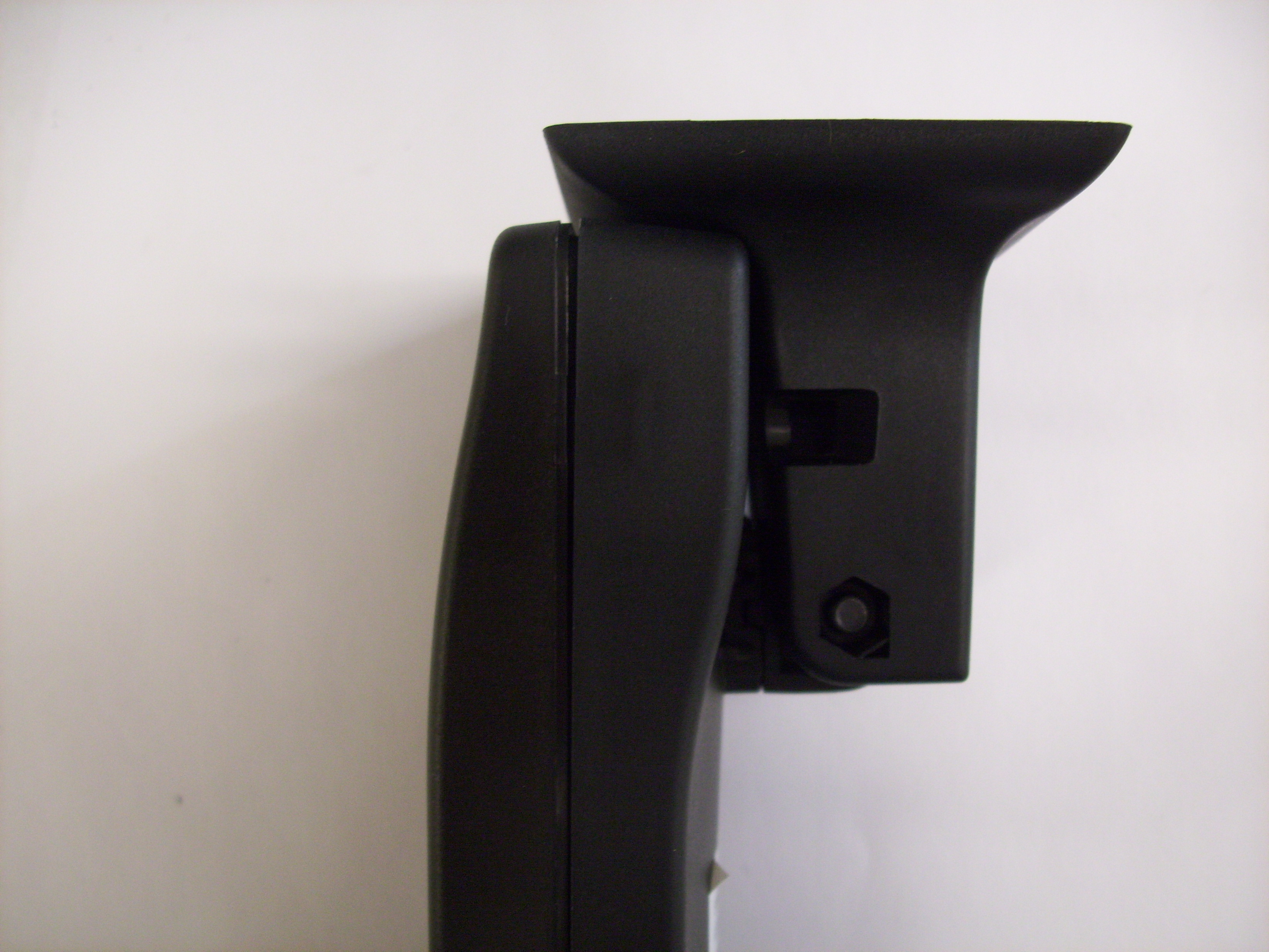
1. Attach Windshield support to the Support Spur using the supplied screw and nut. (Note correct orientation of the window mount)
2. Check the "Final Box" in AdminCenter to make the camera eligible for shipment.
X2 Camera Final Inspection and Packaging
No smudges
put in plastic bubble wrap bag & place sticker on the outside with the serial number
Place in box and put serial number sticker on outside of box
Shipping and Device Assignment
Using the idrive admincenter to ship idrive devices from the factory.
Log in with your user name and password to http://admincenter.idriveglobal.com
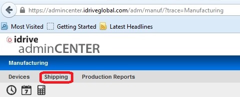
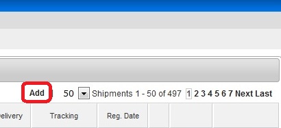
Click on shipping and then click ADD to start the process
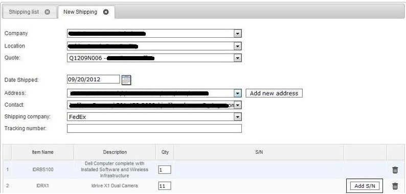
Use the Pull-down fields to select: Company, Location, Quote, Date, Address, Contact, Shipping Company (Tracking Number(s) can be entered later if it is not yet available). Click on "Add S/N" to open the form for device selection.
- We really need the scanner to do this to reduce the errors.
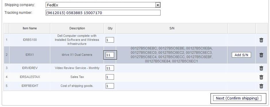
In the device selection form check the box next to the device(s) to be shipped. You can search the list by typing the last 3 characters into the "S/N" box which will highlight the device you are searching for. Once ALL of the devices are selected click on the "X" to close the window.
Verify the correct number of IDRX2 units (the other items ship from elsewhere) and Click "Next(Confirm shipping)"
- New Picture
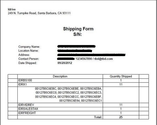
After Confirmation a Shipping form will come up. This should be printed and included with the shipment of the devices to the customer.
- New Picture
Select the "Shipping List" Tab. If you need to add tracking information you must do it before closing out the shipment using the edit button. Select "Close" to assign the cameras to the customer as well as send the automated notification of the shipment to the people on the distribution list. The "Close" process will be performed by Idrive after our review of the shipment.
Done.
<br\><br\>
Appendix A - SD Card Preparation
The X2 Micro SD cards need to be be formatted with the EXT4 filesystem and have the system image placed on them. There are several ways to accomplish this
- SB Shark Duplicator
- Using a Linux system (a virtual machine is installed on the programming station for this purpose)
- A windows PC with a third party driver the recognizes the EXT4 filesystem (not recommended)there is an open source Windows driver for ext3/4 that can be used to read these cards: http://www.ext2fsd.com/ ensure to check the write option at installation time. This often cause system crashes with "the blue screen of death"
- Purchase SD cards that are preprogrammed (not economical base on the quotes we received)
After duplication affix label or stamp with version so there is a difference between programmed and unprogrammed cards.
Use of a Linux System for MicroSD copying
Overview - Any Linux system can be used for staging the Idrive X2 filesystem on the MicroSD card. The filesystem type on the SDcard needs to be EXT4 format (Linux filesystem). There are open source drivers available that allow windows to recognize the EXT4 file system but they very unstable and cause system crashes. It is therefore recommended that Linux be used for the microSD programming. The programming station has Ubuntu Linux installed on it using VMWare (virtual system).
Using VMware for access to Ubuntu Linx
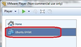
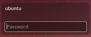
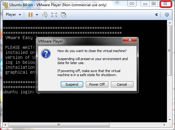
Double Click on the VMware Icon on the desktop, Click "Ubuntu-64bit" to launch the virtual machine, login at the prompt with username (ubuntu) and password (none)(the word, not blank)
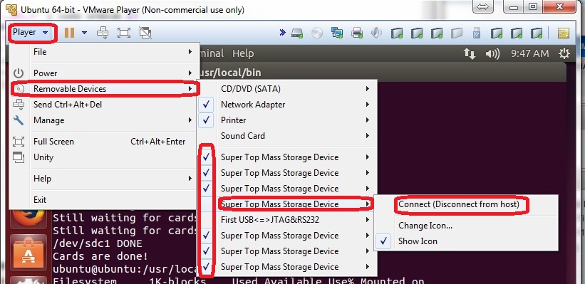
Ensure the removable devices are assigned to the virtual machine and not windows ("check mark" means connected to virtual machine)
Player> Removable Devices> SuperTop Mass Storage> Connect (Disconnect from Host)
- Number of devices will vary based on hardware and the number of MicroSD cards inserted
- "SuperTop" is the name of the SD adaptor in use. This will vary depending on the adapter used
- Host is the windows system
- once the removable device is attached to the virtual machine it should stay assigned for the entire session
![]() Click on the X2 MicroSD Programming Icon.
Click on the X2 MicroSD Programming Icon.
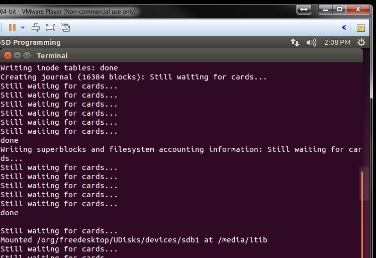 A terminal window will open and the MicroSD card(s) will be formatted and the filesystem (OS) written to them. While this is happening you will see "Still Waiting for Cards..."
 Upon successful completion you will see Cards are done! The amount of time for the process will depend on the number of cards being programmed at the same time.
Use of SDShark Duplicator for MicroSD programming
WireShark use for MicroSD programming
Use of USB Image Tool
http://www.alexpage.de/usb-image-tool/download
http://www.alexpage.de/usb-image-tool/faq
1) double click on USB Image Tool.exe
2) Use Device Mode
3) Click on Restore
5) Select path to Image file
Appendix B - Idrive X2 Programming Station Documentation
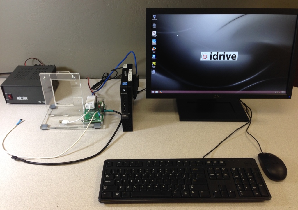
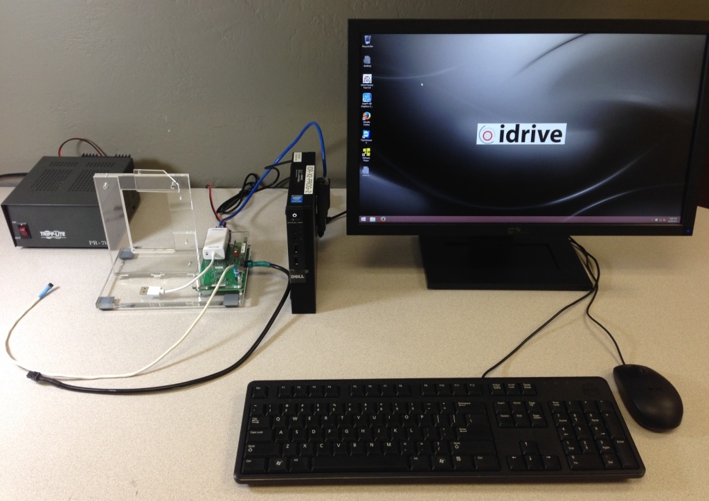
Programming Station Components
| X2 Programming Station Components |
|---|
| Windows 8 Computer with Monitor and speaker(s)(see requirements below) |
| Bar Code Scanner |
| Lens Focus Charts |
| Micro SD card reader |
| Idrive X2 Programmer Fixture |
| I/O Loopback Test Adapter |
| DC 12V/1A LINEAR power supply |
| USB type B cable |
| USB to Ethernet adapter |
| Cat5 Cable |
| Power cable for X2 |
| X2 Serial Programming cable |
<br\>
X2 Programming Computer Setup
Computer Hardware Minimum Requirements
- Monitor (needs to support 1600X1200 screen resolution)
- Speaker(s)
- Windows 8.1 Professional recommended
- 1GB RAM
- 100 GB Hard Disk
- 2 Network Interface adaptors (NICs)
- Keyboard and Mouse
Network Configuration
- Network Connection to the Programming Fixture
- IP address: 192.168.0.10
- Subnet Mask: 255.255.0.0
- Default gateway: Blank
- Network Connection with access to internet
- DHCP or as required by location
<br\>
Computer Software Requirements
- TeamViewer V11 (http://www.teamviewer.com ) - personal license. Install TeamViewer - during setup you need to choose the Personal license installation!
- Idrive Factory Tools 3.3.1
- Future Technologies USB Driver for X2 Programming Fixture (http://www.ftdichip.com/Drivers/VCP.htm)
- Firefox Web browser (https://www.mozilla.org/en-US/firefox/new/)
X2 Programming Fixture Setup
<br\><br\>
Computer Connections
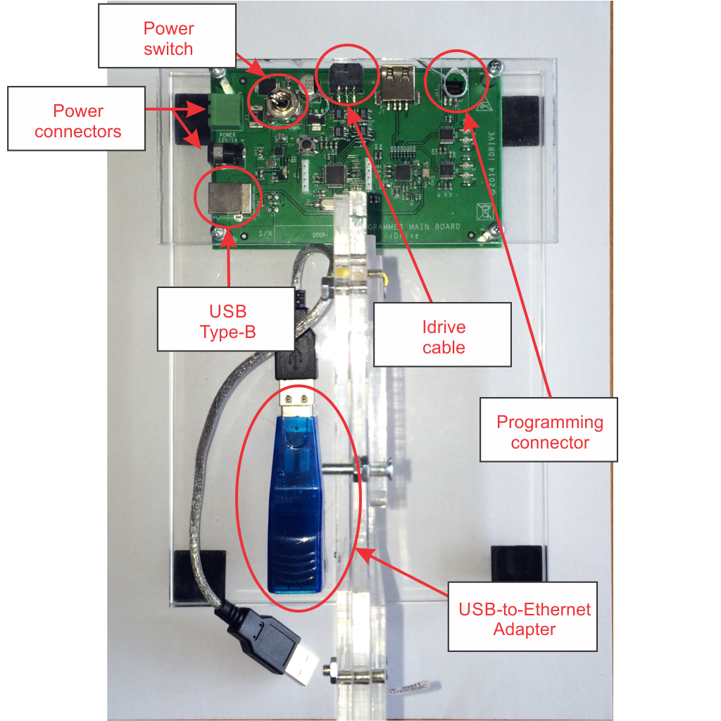
- Connect the 12volt Power Supply to the Power Connector
- Connect the USB cable from Programming computer to USB Type B connector
- Connect the USB-to-Ethernet Adapter to the Programming Computer with a Cat5 (Network) Cable
Idrive Camera Connections
- Connect "Idrive Cable" to the Device to be programmed
- Connect the "Programming Connector" to the Device to be programmed
- Connect the USB-to-Ethernet Adapter to the Device to be programmed
<br\><br\><br\><br\>
Turn On the Power switch and leave the programmer on for the batch of boards.(you do not need to turn it off to program the next board)
X2 Programming Fixture Documentation
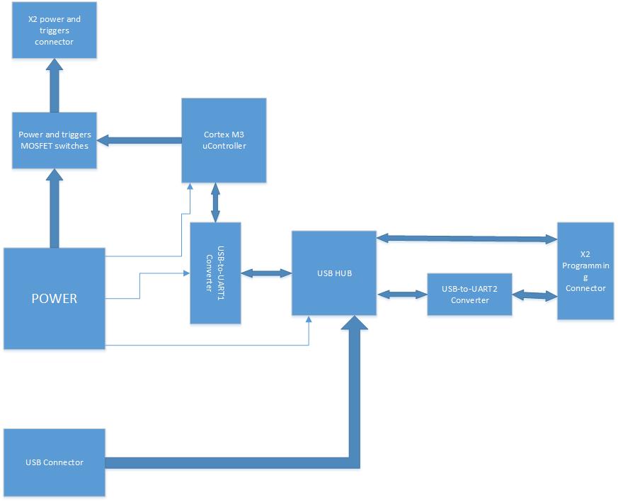
On X2 programming connector there are 2 communication buses present:
- one bus is PC-to-X2 serial connection (using USB to UART converter)(serial one) is used to communicate(send commands receive messages) with U-boot(bootloader) and/or X2's Linux OS (linux console).
- the second bus is PC-to-X2 direct USB connection (USB OTG port of X2 processor)is used only for initial bootloader NAND IC programming or as system recovery in case the bootloader present in NAND IC is corrupted.
When using Factory tool Auto Install or Install Bootloader features, first operation executed by FT is to erase the old bootloader from NAND.
After erasing old one, if X2 processor is not able to "see" the bootloader present in NAND, it enters the system recovery mode by activating it's USB OTG port for a Processor-to-PC direct connection ;this should be confirmed on PC by enumerating a "HID-compilant vendor-defined device" on Device manager (see picture attached).
NOTE: The "HID-compilant vendor-defined device" will appear only when NAND bootloader is missing or corrupted.
From log messages displayed by your Factorytool, it seems that first step (bootloader erase) was performed and the X2 processor USB OTG connection is rejected by PC (please observe "Device Arrival" , "Device Removal" messages present in the log).
In my opinion this is a PC USB problem , for confirmation you can test a known working fixture (for ex: RMA fixture) on this PC.
The fact that shunting the USB-to-serial converter's port does not provide feedback is also indicating PC USB problems.
The only components "involved" in this connection are:
1. Programmer's USB HUB -this is working because you can see/access the USB-to-UART converters.
2. Cable - if cable is bad no HID-compliant device message will ever appear.
3. X2 Processor - known to previously work.
4. PC station
Appendix C - Idrive X2 Secondary/Final Test Station Documentation
Secondary/Final Test Station Components
| X2 Secondary/Final Test Station Components |
|---|
| Windows 8 Computer with Monitor and speaker(s)(see requirements below) |
| USB to Ethernet adapter (Second NIC on Computer) |
| Bar Code Scanner |
| Idrive X6 Test Fixture |
| DC 12V/6A power supply |
| 6 Power cables for X2 |
| Zebra barcode printer |
| USB type B cable (for Printer) |
| 802.11g Wifi access point |
| Cat5 Cable, POE, Shielded FTP Cable |
<br\>
X2 Secondary/Final Test Computer Setup
Computer Hardware Minimum Requirements
- Monitor (needs to support 1600X1200 screen resolution)
- Speaker(s)
- Windows 8.1 Professional recommended
- 1GB RAM
- 100 GB Hard Disk
- 2 Network Interface adaptors (NICs)
- Keyboard and Mouse
Network Configuration
- Network Connection to the Programming Fixture
- IP address: 192.168.0.10
- Subnet Mask: 255.255.0.0
- Default gateway: Blank
- Network Connection with access to internet
- DHCP or as required by location
<br\>
Computer Software Requirements
- TeamViewer V9 (http://www.teamviewer.com ) - personal license. Install TeamViewer - during setup you need to choose the Personal license installation!
- Idrive Factory Tools 3.2.x
- Firefox Web browser (https://www.mozilla.org/en-US/firefox/new/)
X6 Secondary/Final Test Fixture Setup
Computer Connections
- No Direct connection from the X6 Fixture and the PC
- Idrive 802.11g Access point
- Internet connection
Idrive Camera Connections
- Connect "Idrive Power Cable Cable" to the Cameras to be Configured/Tested
<br\>
Turn On the Power switch and leave the programmer on for the batch of boards.
Wireless router Setup
If a wireless router is used with the V7 programmer a small network hub is required to share the idrive programmer NIC on the computer.
- LAN IP address 192.168.0.1
- Network Mask 255.255.0.0
- Default Gateway Blank
- SSID bwifi
- No DHCP
- No DNS
- No WAN settings (not in use)
<br\>
Appendix D - Idrive X2 Factory Tool Documentation
Launch the Idrive Factory Tools 3.3.x Application
![]() Double click the icon on the Desktop to open the application
Double click the icon on the Desktop to open the application
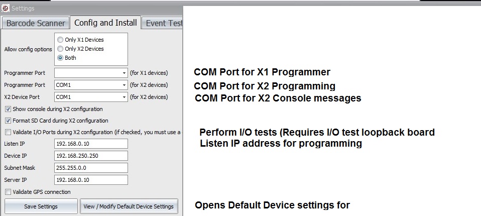
Configure Application Settings for the Programming Station
Idrive Development password idrive2#dev
Set the port number for the Barcode scanner. (Normally Human Interface Scanner)
(Port number can be checked in "Control Panel> System and Settings> Administrative Tools> Computer Management> Device Manager> Ports)
(Port numbers can be checked in "Control Panel> System and Settings> Administrative Tools> Computer Management> Device Manager> Ports)
Appendix E - Idrive X2 Labels/Printing Documentation
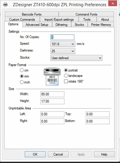
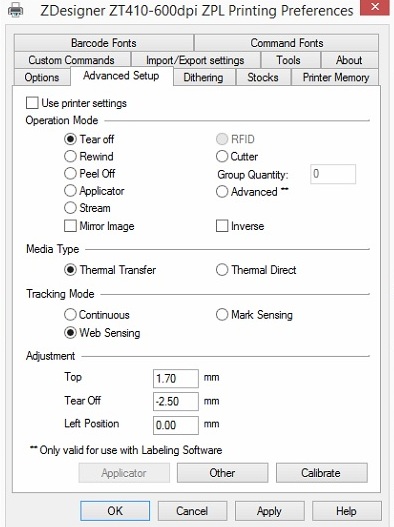
ZT410 Printer Configuration
Label for X2 Main PCB serial number/bar code label
1 ea Brady THT-103-727-10 - Placed on X1 Main Board at build time
Requires Ribbon R6000
1"X.25", White, Thermal, High Temp Polyimide, 1 per row, 3" core, 10k per roll
Brady Product description: http://www.bradyid.com/bradyid/pdpv/THT-103-727-10.html
Catalog page: http://www.bradyid.com/downloads/ISD_148.pdf
- Serial number Example: 025821100001
- Bar Code of serial number (Code 128)
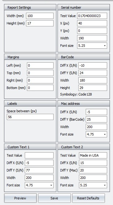
Label for X2 External serial number/bar code/MAC address
3 ea THT-3-423-10 - for X2 Case, Plastic bag, Box exterior
1"X.37", White, Thermal, B423 Polyester, 3 per row, 3" roll core, 10K per roll
Brady Product description: http://www.bradyid.com/bradyid/pdpv/THT-3-423-10.html
Catalog page: http://catalogs.bradyid.com/app.php?RelId=6.6.1.7p1.22&BookCode=sfe15flx
Order from: https://www.biscoind.com/store?goto=1#view1 (search for THT-3-423-10)
Requires Ribbon #R6007 http://www.bradyid.com/downloads/ISD_184.pdf
- Serial number Example: 025821100001
- Bar Code of serial number
- MAC Address of Wifi Module
- Made in USA
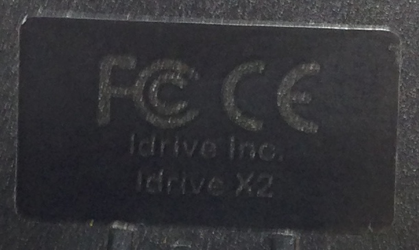
Label for X2 FCC/CE compliance
- FCC logo CE Logo
- Idrive Inc.
- Idrive X2
Label for X2 GSM module serial number/bar code/MAC address
2 ea THT-xxx0 - for GSM Module Case, Plastic bag
1.5"X.25", White, Thermal, B423 Polyester, 2 per row, 3" roll core, 10K per roll
Brady Product description: http://www.bradyid.com/tbd
Catalog page: http://www.bradyid.com/downloads/tbd
Order from: https://www.biscoind.com/store?goto=1#view1 (search for tbd)
- IMEI number Example: IMEI: 861075020842522
- Bar Code of IMEI
- ICCID (SIM serial number?) Example:8940011410302975328F
Where does the label go? Windshield side next to red tape?
