Manufacturing:AI Device Manufacturing and Programming Process
AI Device Manufacturing and Programming
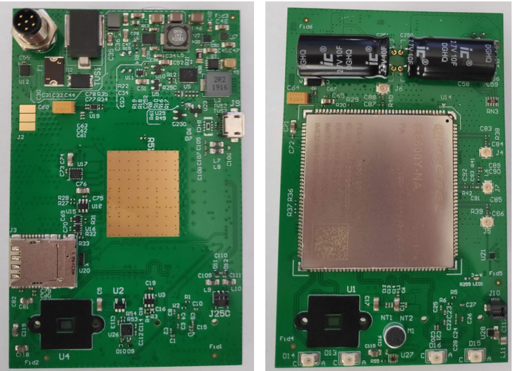
INITIAL ASSEMBLY AI BOARD
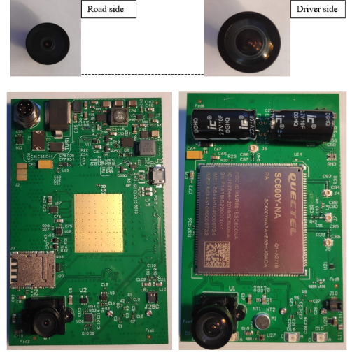
1. Attach the S/N label on the dedicated area of the “Road side” of the Main Board.
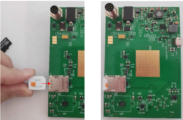
2. Insert (by pressing) the Micro SIM into the SIM / SD socket on the Road Side of the Main Board.
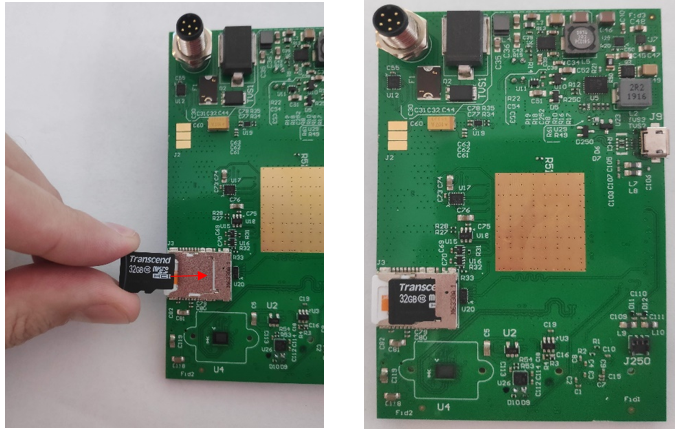
3. Insert (by pressing) the 32GB Micro SD card into the SIM / SD socket on the Road Side of the Main Board.
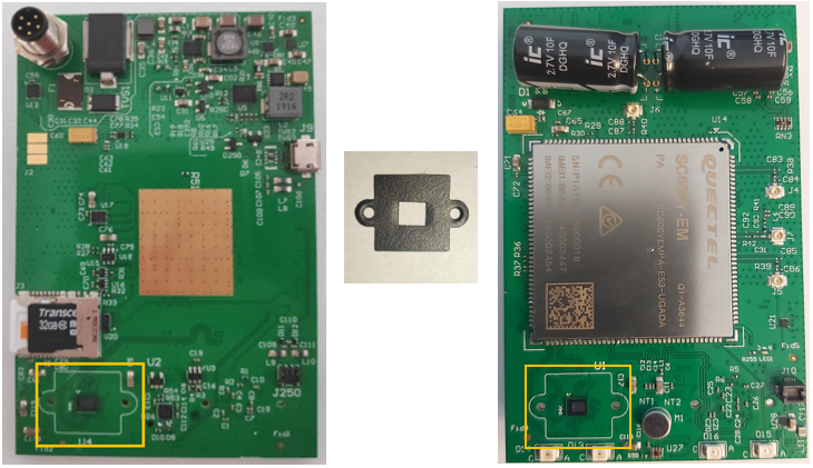
4. Mount (by the adhesive tape present on the back) the two Gaskets on the destinated area of both “Road” and “Driver “sides of the board.
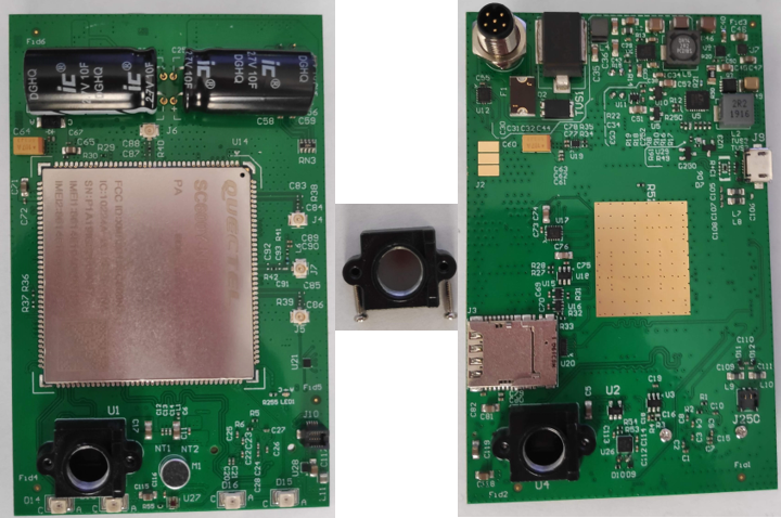
5. Mount the two Lens Holders (by screwing) on both sides of the board.
Screwing is made from the behind of each lens holder, through the dedicated holes with a torque of 0,2 Nm.
6. Insert the proper lens (by screwing) in the correct side of the Main board, into the Lens Holders.
After programming and focus, lenses are glued.
7. Advance the Top Level AI Main Board PCB assembly to the AI Programming Station
AUTOMATIC INSTALL AND CONFIGURATION (VIA FACTORY TOOL)
Notes: The Automatic install performs the following:
•installs the AOSP and the Firmware, gets device configuration from the Idrive AdminCenter (IP address, serial number etc.);
•tests triggering on the yellow, blue and green wires;
•provides lens focus mode so both lenses can be focused and glued.
!For this step, DO NOT use Developer Mode!
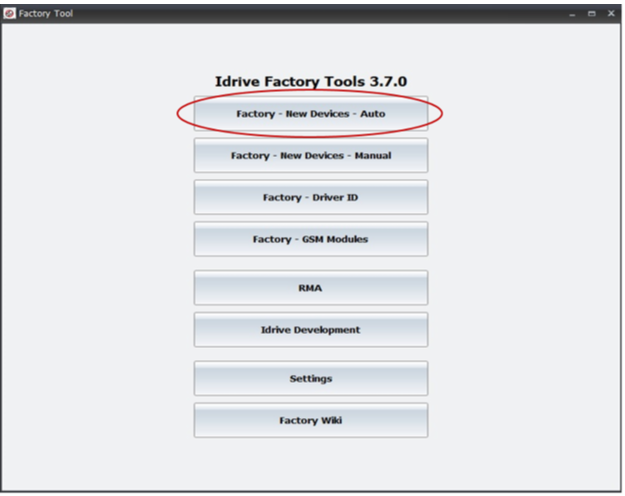
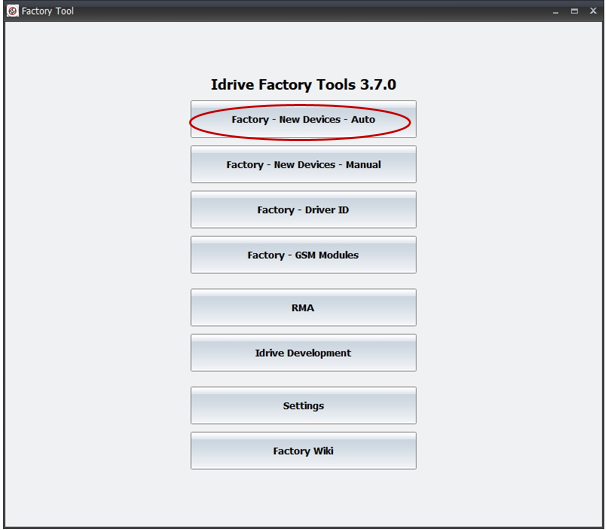
1. Click on the Factory - New Devices - Auto button
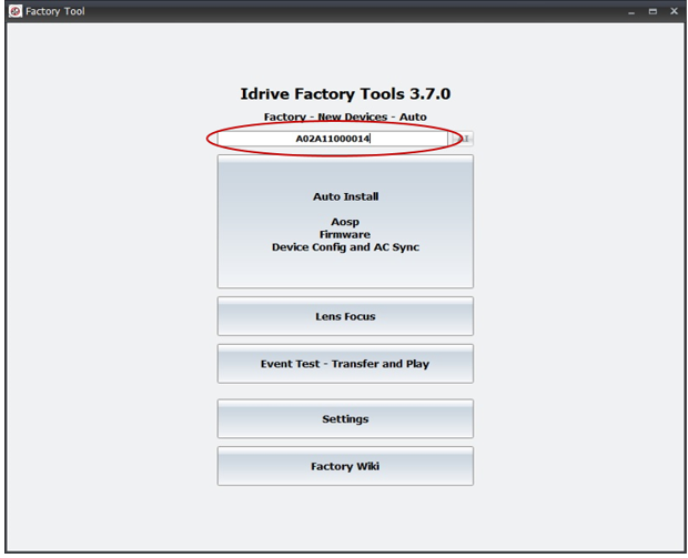
2. Scan using the bar code scanner the Bar Code label present on the Main board and press Enter.
If no bar code scanner is available, manually type the serial number from the bar code label into the serial number input field.
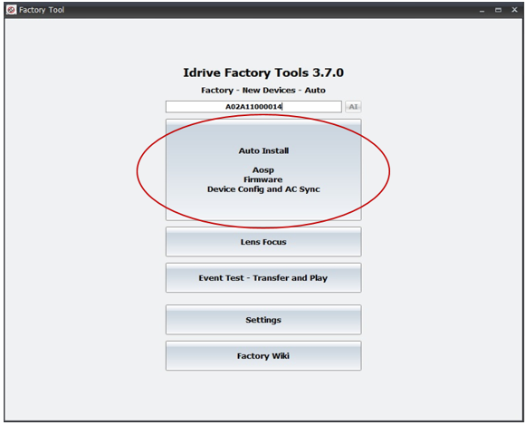
3. Click on the Auto Install button and the Automatic Install window will open.
If the SN have already been introduced (device has already passed through one or more programming steps), a warning message will be displayed asking if you want to Continue or not. Continue if you want to reprogram the device, cancel if you introduced once more the SN by mistake.
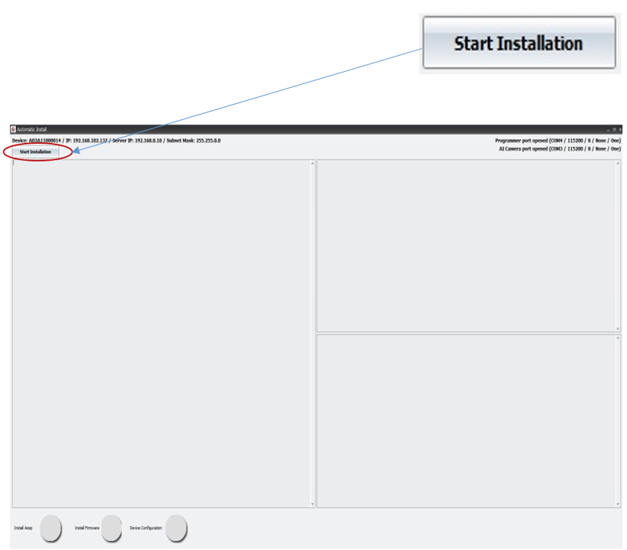
4. In the Automatic Install window, Click on Start Installation button.
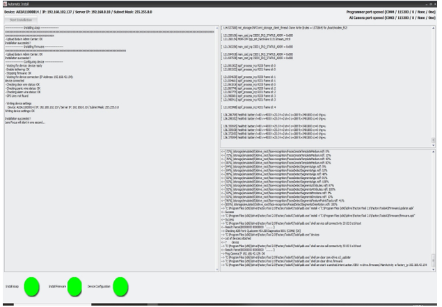
Installation and Configuration process steps:
1. Install AOSP
2. Install Firmware
3. Device Configuration
AI camera successfully installed and configured when all three buttons are GREEN.
If all the steps are successfully completed, the program will enter into Lens Focus mode.
If any of these steps fails, the program will stop and give an error. Common errors are:
-Missing or corrupt storage SD card
-Serial cable not connected or incorrect polarity
-USB NIC or Internet connection missing
-I/O ports tester board missing
-Any assembly or incorrect component error
! In case any of the 3 steps fail (button will be red instead of green), there are two options (corrective actions):
1.Repeat the entire process by clicking on Start installation button in the Automatic Install window and the AOSP installation, Firmware installation and Device Configuration will be redone automatically.
2.Repeat manually only that specific step that failed:
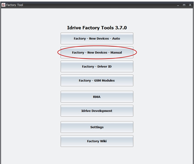
a) Click on Factory - New Devices – Manual;
b) Scan barcode
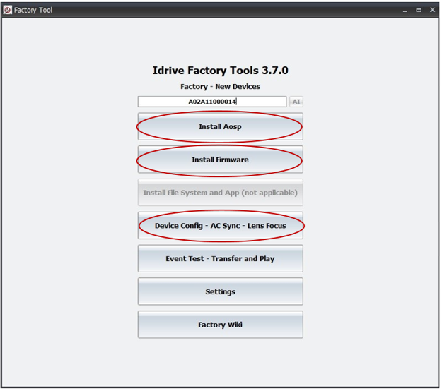
c) Depending on the step that failed, click either on Install Aosp button -> Start installation, either on Install Firmware buttonStart installation, either on Device Config – AC Sync – Lens Focus button -> Start configuration.
In case that the first step failed (Install Aosp), recommended would be to repeat automatically the process by clicking on Start installation button in the Automatic Install window.
Lens Focus
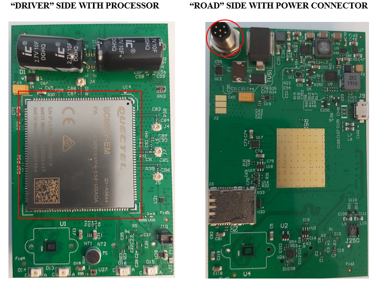
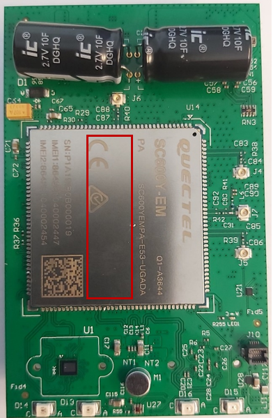
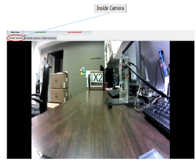
1. Select "Inside Camera" Tab and Focus the “Driver side” Lens (“Driver side” is the side containing the Processor).
The focal length for the inside camera should be ~1.5 meters
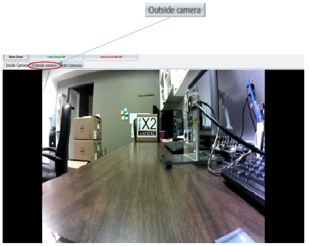
2. Select "Outside camera" tab and Focus the “Road side” Lens (“Road side” is the side containing the Power Connector).
Focus using the provided Idrive Focus Chart. Distance to chart can be 3,6,9 feet but the farther the better.
Optional: Use zoom mode (Show zoom button) to ensure accurate focus.
In Both Cameras tab, you can visualize both “Driver side” and “Road side” cameras on the screen (the screen will be splitted in two).
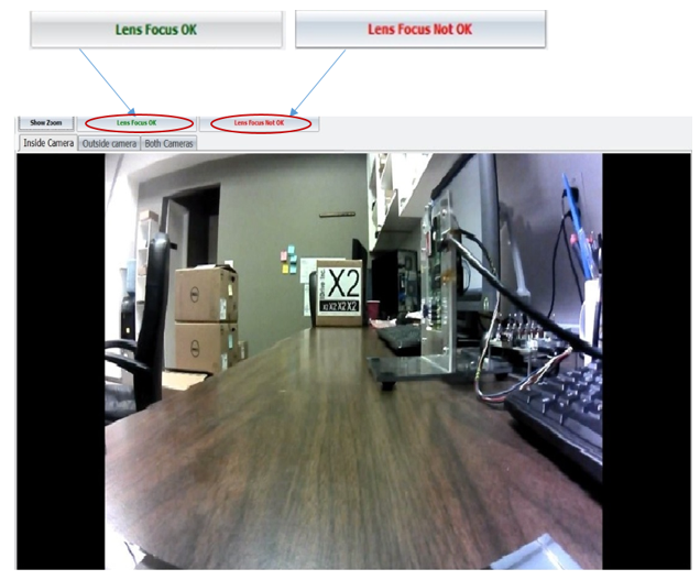
3. If images are focused and clear (the outside test text is accurate and readable), click on the "Lens Focus OK" button and the focus mode will close.
If one of the images or both images are not clear, or if the Streaming is not loading (“Loading…Please wait!” message is displayed), click on the "Lens Focus Not OK" and the factory tool will exit focus mode, so corrective actions can be taken.
! Corrective actions: Repeat manually the 3rd step: Factory - New Devices – Manual -> Scan barcode -> Device Config – AC Sync – Lens Focus -> Start Configuration
4. Once focused, fix each lens with a drop of super glue. Test the lenses after several minutes to ensure they have taken the glue and cannot be moved (it means the glue is dried).
5. Remove the device from the test fixture (programmer fixture).
6. Advance the device to Final Assembly step.
FINAL ASSEMBLY AI CAMERA
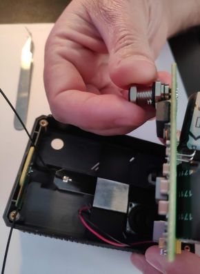
1. Remove (by screwing) the screw nut from power supply connector on the Main board and set it aside.
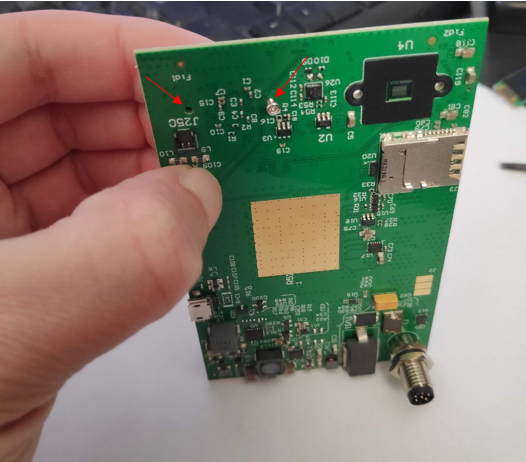
2. Connect speaker wire (red and black wire) into the J250 socket on the “Road” side of the Main Board.
3. Assembly Main board with the “Driver” side up into the inferior case by gently pressing on Main board and by pulling the edges of the case.
4. Tightens the screw nut removed in step 1 on the power supply connector (torque 0.2 Nm).
5. Connect the wires into the sockets on “Driver” side of the Main board:
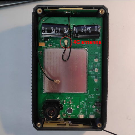
a.Connect 4G antenna – insert wire 1 in J6 socket on Main board;
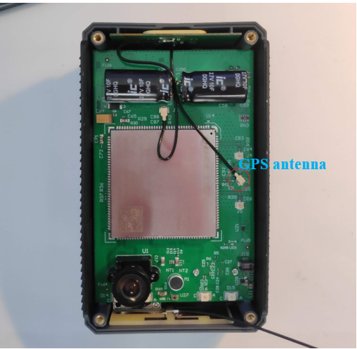
b.Connect GPS antenna – insert wire 2 in J7 socket on Main board;
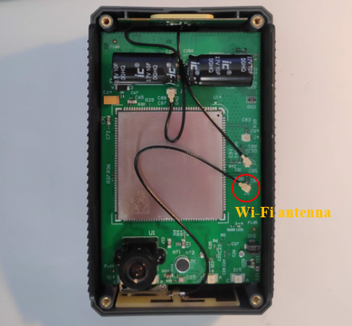
c.Connect Wi-Fi antenna – insert wire 3 in J5 socket on Main Board.
6. Mount the Display module into the dedicated socket.
Remove the plastic protection foil from the display.
7. Mount by screwing the superior case (use torque 0.3 Nm).
8. Advance assembled AI cam to Final test process.
FINAL TEST (VIA FACTORY TOOL)
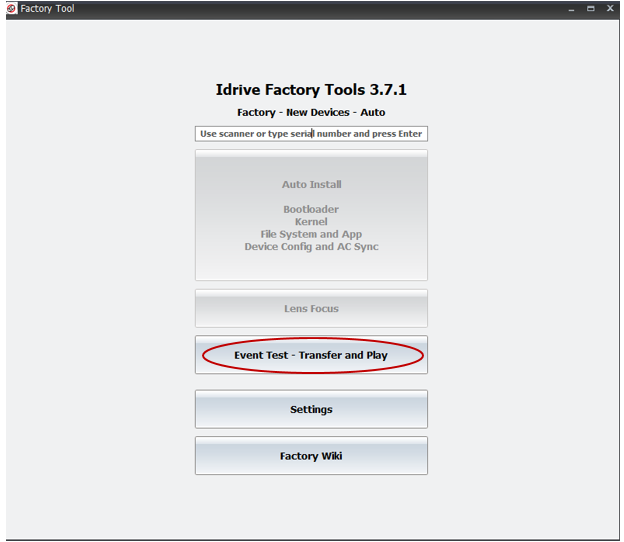
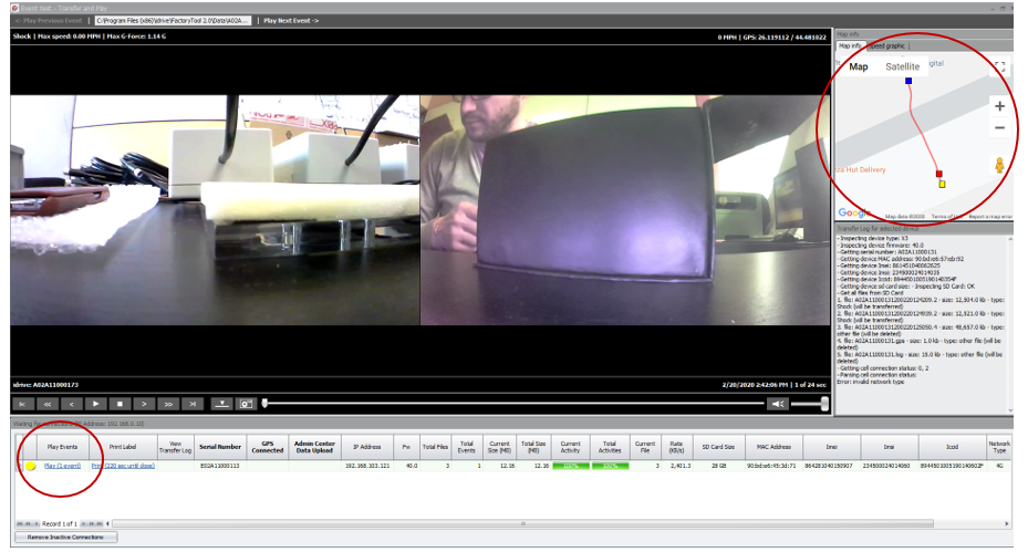
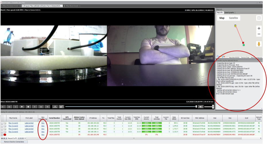
1. Open Factory Tool -> Factory - New devices – Auto -> Event Test – Transfer and Play (event test window will open – see at point 7)
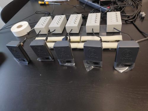
2. Connect 5 assembled AI cameras to Switch boxes power supplies (Power and Ignition are OFF).
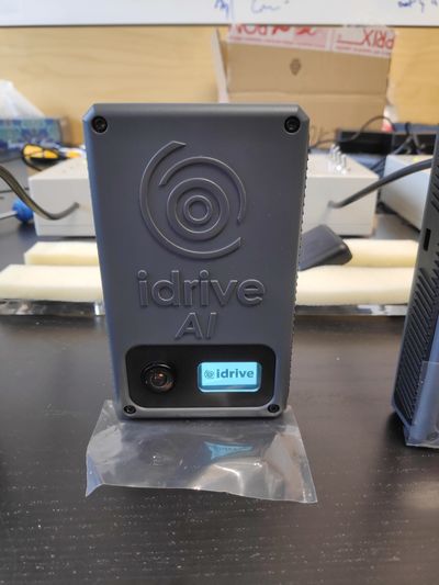
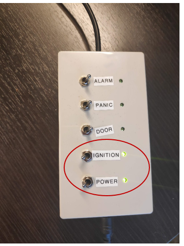
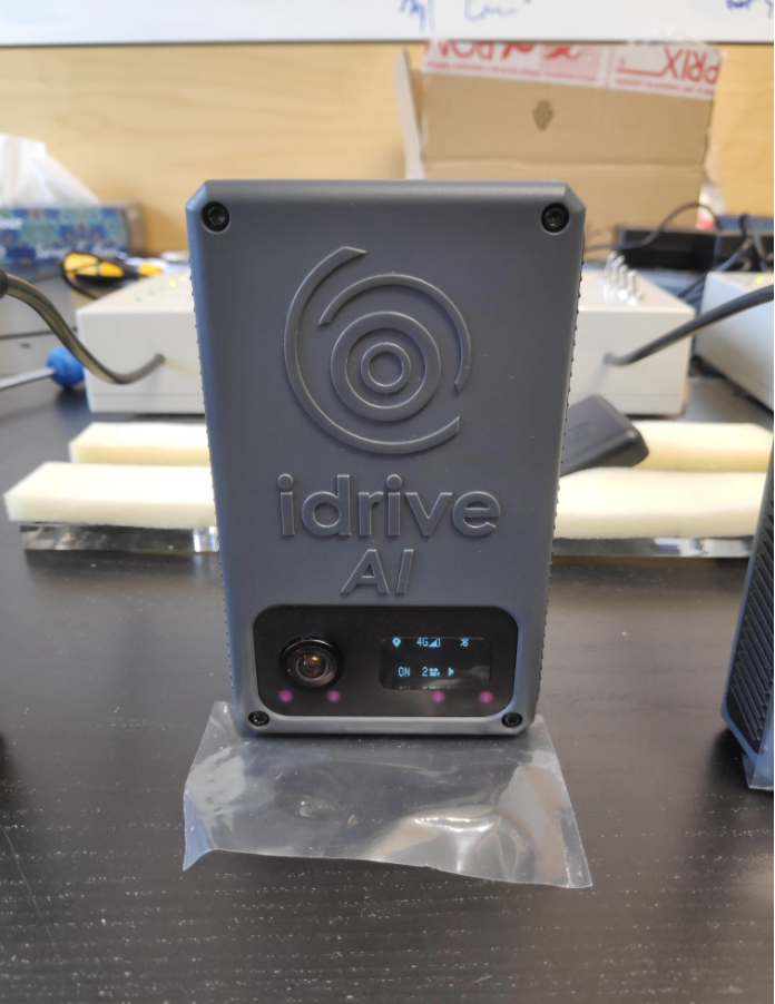
3. Switch Power and Ignition ON -> AI cameras will start to boot (Idrive logo will be displayed).
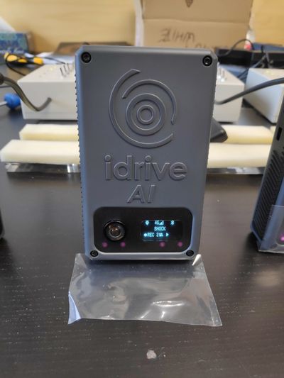
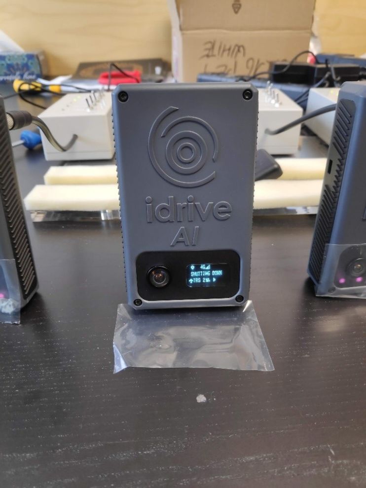
In this phase, AI cameras connect to GPS and to network (2G/3G/4G). The operator must pay attention to the cameras screens to assure that connections are available, and that all the icons are displayed and there is no error code – See picture below.
4. Trigger a SHOCK event by pulling (shaking) each AI camera backward and forward (once or twice)-> Message SHOCK will be displayed on the screen, moment when the camera starts recording the event.
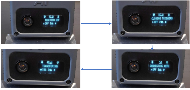
5. After triggering and recording the SHOCK event (display gets back to normal), Switch Ignition OFF for AI cameras.
In this phase, AI cameras connect to Wi-Fi and start transferring. A text with IGNITION OFF followed by CLOSING TRIGGERS, by CONNECTING WIFI and by TRANSFERING along with specific icons, will be displayed on the screen.
6. In the event test window, click on Play for each of the AI camera in the Play events area -> the record of the SHOCK event will be played.
Verify the focus of both lenses (image clarity). If the image is clear, lens focus was done properly. If not, the camera must be put aside. Check also if GPS route was recorded.
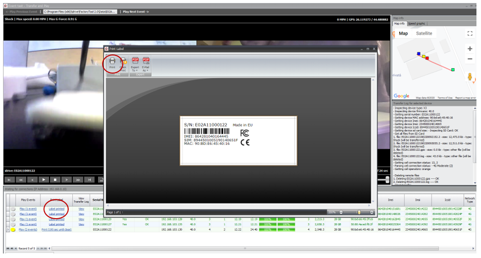
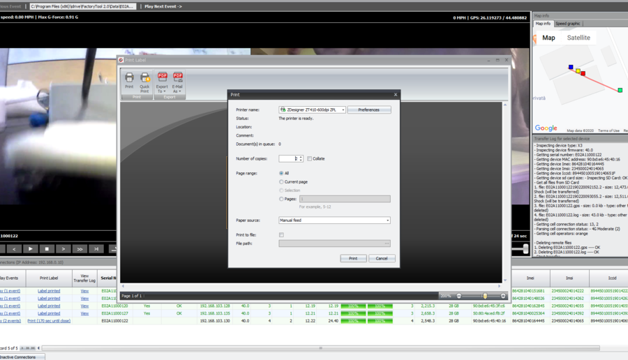
7. If lens focus OK and GPS route recorded -> Click on Label Printed – Print and print 2 labels. Close the window.
There will be displayed 2 messages: one for label print confirmation and one for beep confirmation.
If label was not printed, click NO and try again to reprint the label. Camera starts to beep only if label printed was confirmed. Once label print and beep confirmed, serial number text row turnes green. If there is no beep, it means that the camera has a problem with the speaker.
8. Camera will shut down automatically (SHUTTING DOWN message will be displayed) -> Switch Power OFF and Unplug the camera.
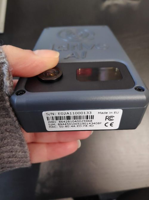
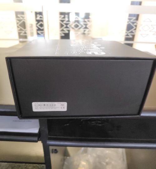
9. Apply one label on the bottom of the AI camera and one on the right side of the Final box.
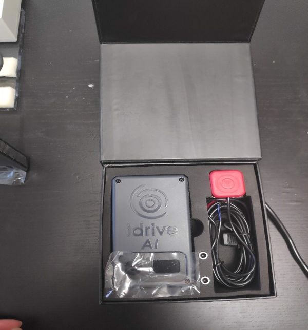
10. Put the AI camera into the Final box.
ISSUES:
- AI camera doesn’t boot (display is off): verify power circular connector if it’s properly soldered to the board.
If yes, AI camera has a problem with the display -> display needs to be replaced
If it’s not, manually redo the soldering of the connector.
- AI camera appear with red text in the event test window, click on View in the View Transfer Log and see what error occurred.
First, redo the final test (without another shock trigger). If camera didn’t pass second time either, try solutions below:
- Network error
verify if the 4G antenna connector is OK and properly inserted (visual inspection).
verify if the cable is properly soldered to the antenna.
If both above OK -> replace SIM card.
If one or both above are NOK, replace connector/replace cable/manually redo the soldering.
- GPS error
verify if the GPS antenna connector is OK and properly inserted (visual inspection)
verify if the cable is properly soldered to the antenna.
- Infinite loop = HW problem which requires a close HW verification.
- Lens focus NOK -> Disassemble the AI camera and replace entire gasket + lens holders + lens assembly.
- AI camera doesn’t beep = speaker problems -> verify if speaker connector is OK and if it’s properly inserted (visual inspection).
Radu Notes
The AI programmer is mandatory only one time when the board comes from China with the default chinese AOSP. Once the AOSP is overwritten with our AOSP, the programmer becomes optional.
You need a micro usb cable in order to connect camera to a computer usb port, a power source for AI camera and a computer with Windows 10 (preferable).
Factory Tool Installation
Install Factory Tool
Download and install the latest Factory Tool from Admin Center
Firmware
Firmware folder is auto-populated by the Factory Tool installer and should have the following structure:
- firmware.apk represents the current firmware version (43.2.309-3.0)
- updater.apk is a background application taking care about firmware and aosp upgrades / firmware crashes / background staffs. The current version is 1.0
- idrive_root is the place where we keep different files (neural networks, settings, etc)
- firmware.apk should be replaced every time when a new stable firmware is released. For example, if you have a new update.apk file, you can rename this file and copy it over firmware.apk. You have also to copy the same file over idrive_root/recovery.apk file
- The same mechanism should be used if we will upgrade updater.apk. That apk should also be copied over idrive_root/recovery_updater_app.apk.
- Any file from idrive_root folder is replaceable. In the future we can add / remove / replace any file from idrive_root
Install the Android OS
Download and install the latest AOSP from Admin Center
Unzip the ASOP archive
Copy the files to C:\Program Files (x86)\Idrive\Factory Tool 2.0\FactoryToolsAI\Aosp
Every time when a new AOSP is released, the files from Aosp folder should be replaced with the new files.
FT Configuration
Select Idrive Development > Settings (password > idrive2#dev)
Disable Passwords ( if applicable)
Click on Passwords tab and disable
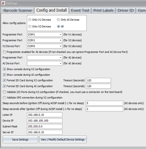
Config and Install
Uncheck "Programmer enabled for AI devices"
The Factory Tool is documented, but I don't have the documentation now 🙂 (Alexandra will send you all documents tomorrow morning)
However the process is very similar with X2. There are AI settings in Idrive Development->Settings->Config and Install (see below)
(DO NOT CHANGE the "sleep seconds" fields for AI devices only).
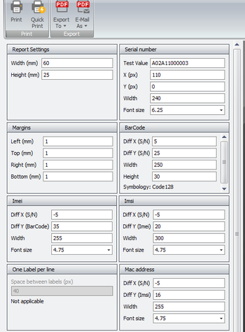
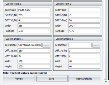
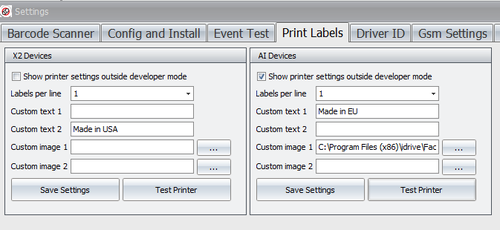
Factory Tool Print Settings (Santa Barbara)
Idrive AI Labels Windows Configuration
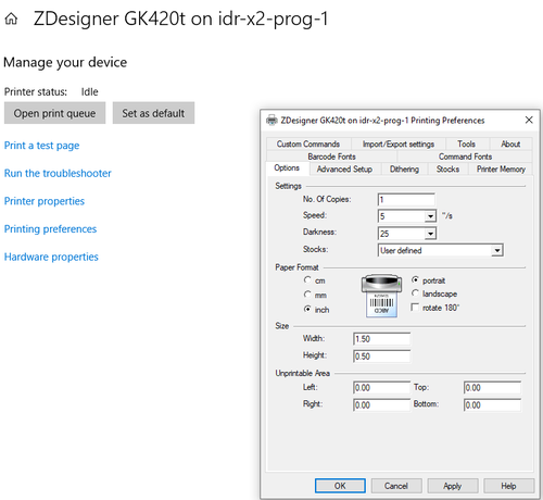
Add the Printer
Settings > printers
Add printer>
\\idr-x2-prog-1\Zdesigner GK420t
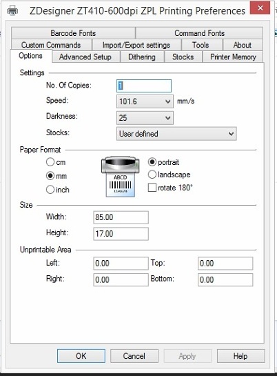
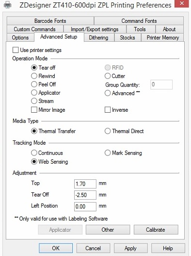
Click on printer and Manage > Printing preferences Options> Darkness 25, Width 1.5" Height .5"
GK420T Printer Configuration (Santa Barbara)
Install Zebra Setup Utilities (Not needed for Factory Tool)
Label supplies for GK420T printer in RMA area
https://www.zpsstore.com/ShoppingCart.asp
https://www.bradyid.com/en-us/family/cps-3053222 (In use in RMA Area)
Zebra Part #: 10011693
Label Size (WxH): 1.5" x 0.50"
Labels Per Roll: 9,420
Rolls Per Case: 4
Core Size: 3"
Outside Diameter: 8"Zebra Z-Ultimate 10011693
- NO perforation between label
Thermal Ribbon:
Zebra 5095 Performance Ribbon
https://www.barcodesinc.com/search.htm?search=05095GS06407&v=1
