Idrive AI (Artificial Intelligence) Installation and Operation Guide
Copyright information
This document contains proprietary information that is protected by copyright. No part of this document may be photocopied, reproduced, or translated to another language without the prior written consent of Idrive Inc. Copyright © 2020 Idrive Inc.
This product incorporates copyright protection technology. Use of this copyright protection technology must be authorized by Idrive Inc. Reverse engineering or disassembly is strictly prohibited. Information in this document is subject to change without notice.
Warnings
Please read the following carefully regarding proper use of the product and ensuring the user’s safety.
1. Use the idrive device only for its intended purpose.
2. Do not disassemble, attempt to repair, or alter the Idrive device. When malfunctions, errors, or other damage is found to be attributable to a user, said user may not be eligible for after sale service.
3. When cleaning the inside of a vehicle, do not spray water or any other cleaning product directly onto the Idrive device. It may cause damage, fire, or electric shock.
4. Keep the Idrive device away from chemicals or detergents as they may change the surface of the product or ruin internal components.
5. Do not insert any foreign objects into the Idrive device. Severe impact, shock, or other foreign matter may cause damage to the Idrive device.
6. When foreign matter blocks the lens, normal operation is impossible. Always ensure that the lens is free of any contaminants or obstruction. Other objects placed around the camera may be reflected off of the window and included in the image, so please do not leave unnecessary objects around the Idrive device.
7. The product will not operate properly if its position changes. Make sure the product is installed securely and do not expose the device to excessive shock. Do not move the device after installation.
8. Staring at or operating the product while driving is dangerous and may cause an accident.
9. Keep the product away from excessively humid or salty environments.
10. This product uses high definition cameras. Sudden changes in light levels, such as entering or exiting a tunnel, may result in temporary image quality degradation. Excessive or insufficient light may also reduce image quality.
11. Excessively tinted windshields may result in poorly defined or distorted images.
12. Use ONLY the supplied cable to connect the Idrive device to the power source, and only as directed in the manual. This product should be connected only to the power inside a vehicle. Any other power source is unacceptable and may cause malfunction or fire and may render the Idrive device ineligible for after sale service.
13. If power to the Idrive device is lost (i.e due to an accident), events may not be recorded.
Idrive AI Camera Components
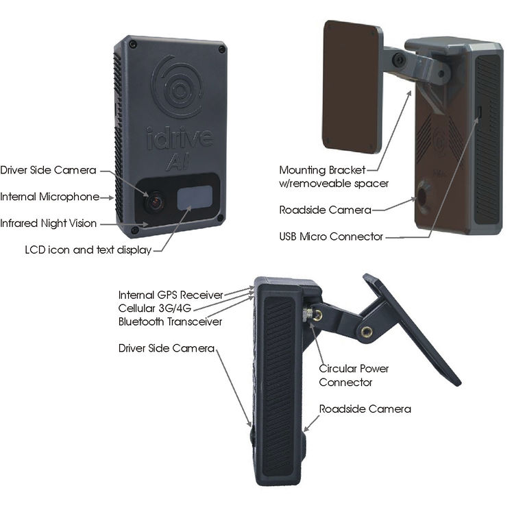
AI Camera
Accessories
Power Harness
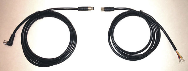
Used to supply power and event triggers from the vehicle to the AI device. The kit comes with the wire harness, fuse holder and fuse. Circular "keyed" power connectors with module ends for easy connection to PowerUp2 accessory.
Wired Panic Button
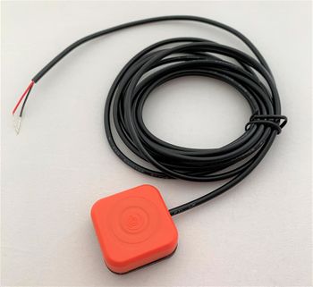
Mounted in easy reach of the driver to manually trigger an event.
NOTE: Idrive Panic Buttons may be supplied with varying colors of wires.
The colors do not determine the function, as the Panic Button is a simply momentary button that triggers the Camera's Blue Wire with 12VDC+
- Please reference the wiring connections section later in this document.
NOTE: A single wire connection change must be made when using existing Panic Buttons to trigger the AI Camera
- Previous X1 and X2 Panic Buttons connected to the Camera's BLUE WIRE and to ground
- AI cameras Panic Button connect to the Camera's BLUE WIRE and 12VDC+
Optional Accessories
OPTIONAL - Power Adapter
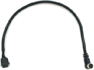
Additionally, a 6 pin Molex to Circular Power Adapter Cable is available as an option that permits previous X1 and X2 Camera power harnesses to provide power and wire triggers to the AI without re-wiring the vehicle.
NOTE: A single wire connection change must be made when using existing Panic Buttons to trigger the AI Camera
- Previous X1 and X2 Panic Buttons connected to the Camera's BLUE WIRE and to ground
- AI cameras Panic Button connect to the Camera's BLUE WIRE and 12VDC+
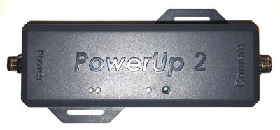
OPTIONAL - Idrive PowerUp2
The Idrive PowerUp is a solid state power conditioner that provides "pure" power and protects Mobile Video Recording electronics from voltage spikes, power surges, momentary power losses, abrupt voltage changes and noise interference on incoming DC power that may contribute to memory loss or crashes.
- It is built with super capacitors that serve as a power reservoir
- The Idrive PowerUP is charged from the cars 12/24VDC charging network by using a step-down 12.5VDC converter
- In the event of a drop in DC voltage, the capacitors will maintain power to X devices for a short period of time.
The Modular connective ends of the AI Power Harness make simple and quick connections to insert the PowerUp2 between the vehicle power and the AI Camera
- "Keyed", male/female ends on the AI Camera, and the AI Power Harness makes it impossible to connect the Circular Power Connectors improperly
Installation Instructions
AI Camera Installation
Before you start
- Read the entire installation guide before installing any Idrive devices.
- Confirm the Idrive Base Station and wireless Access Point(s) are powered on and operational (not necessary for Cellular Only Clients).
- Check the contents of your package and make sure all parts are accounted for and in good condition.
- Verify that the mounting location chosen for the device will not interfere with the driver’s line of sight when operating the vehicle.
- Use the included installation hardware to ensure that the wiring to the device is secure and will not interfere with the safe operation of your vehicle
NOTE: The Idrive units should only be installed by a qualified technician.
Select the mounting location
Correct Position: The proper location for windshield mounting the AI device is on the driver's side, behind the rear-view mirror.
This provides a clear view of the Driver, and the occupant cabin, unobstructed by the rear-view mirror.
IMPORTANT NOTES: HEIGHT POSITION:
- Align the inside camera lens "vertical height" to the match that of an average driver's eyes
- It is acceptable to have the inside camera lens higher than the driver's eyes between 1cm and maximum 4cm (3/8" to maximum 1 1/2")
- It is ok to have the inside camera lens lower than the driver's eyes but with maximum of 2 cm (3/4")
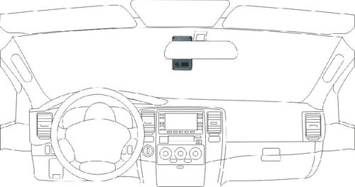 Correct mounting Left-side driver position
Too High: Blocks the driver and occupants faces showing eye and head positions during events.
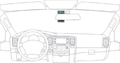 Too High Left-side driver position
Too Low: Reduces cabin view and low hand placement during events. Also places forward viewing camera too low to the front hood reducing field of vision during events.
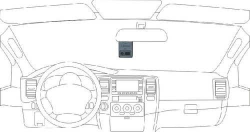 Too Low Left-side driver position
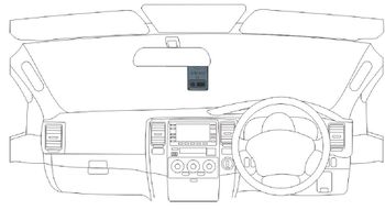
Wrong Angle: Obscures horizon for front viewing and cabin viewing cameras and reduces field of vision at outer edges of the event.
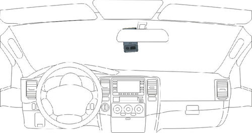 Wrong Angle Left-side driver position
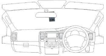
Mounting of the AI Device
WARNING: The adhesive is extremely strong. Once applied to the windshield, it will not come off easily.
Note: if you you need to remove an installed Mounting Bracket, we suggest using a "razor scraper" and a solvent like WD40 to release the adhesive
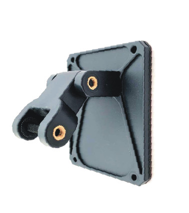
Install the mounting bracket
It is recommended to dry fit the camera using painters tape or sticky notes to create a placeholder on the windshield pryor to permanently adhering to the windshield
When selecting the mounting position do this with the Circular Power Connector attached to the camera to make sure you have the correct space to exit the camera with the connector and not interfere with the windshield or vehicle accessories
- Clean the installation area on the inside of the windshield using an alcohol wipe and wait until the windshield is completely dry. Make sure the glass is clean, dry and the air temperature is at least 50F (10C).
- Position the device and bracket on the windshield and confirm that the unit will hang vertically in the appropriate fashion in relation to the rearview mirror. We suggest marking this position with masking tape.
- Separate the AI Camera from the mounting bracket by removing the hex screw.
- Remove the liner from the foam tape on the backside of the bracket.
- Start by placing only the top edge of the bracket against the windshield, aligned with the your guide marks.
- Press the mounting supports together until the mounting base slightly bows and place to the windshield. Starting in the middle, apply pressure outwards to the left and right. (Do not apply excessive force as it may damage the windshield).
- Make sure there are no large air bubbles under the bracket. You may need to apply additional pressure to remove any large air bubbles.
- Remove any tape residue by using an alcohol wipe.
Install the AI Device into the bracket
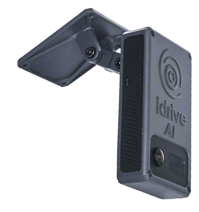
- Insert the mounting section of the AI into the mounting supports of the bracket. Make sure the device is hanging vertically and slightly tilted toward the windshield.
- Insert the bolt into the bracket and tighten.
- NOTE: once the bolt is inserted, the camera's position is rigid. The bolt must be loosened if the position is to be altered.
Routing the Idrive Power Harness
WARNING: When installing the Idrive Power Harness in a vehicle with side or curtain airbags, be certain that neither the cable nor your installation activities interfere with any airbag related mechanisms or might otherwise affect airbag deployment.
The Idrive Power Harness cable is 14 feet long with a Circular Power Connector at one end that plugs into the Idrive device. It is then routed and secured under the dashboard.
The routing of the power cable will vary greatly depending on vehicle type. Choose a routing that will work the best for your particular application.
Start just above the rear view mirror, route the cable under the window trim or headliner across and down the door pillar.
Route the cable out from underneath the trim and under the dashboard.
Note: You may need to remove the trim to route the cable. When reinstalling, be careful not to damage the trim clips or the cable. Keep the cable away from sharp edges and moving parts.
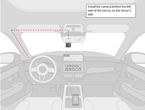
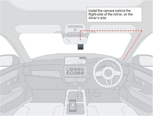
Idrive Wiring Diagram
Attach wires to the following sources in vehicle as shown below giving attention to a Left-side driver position or a Right-side driver position
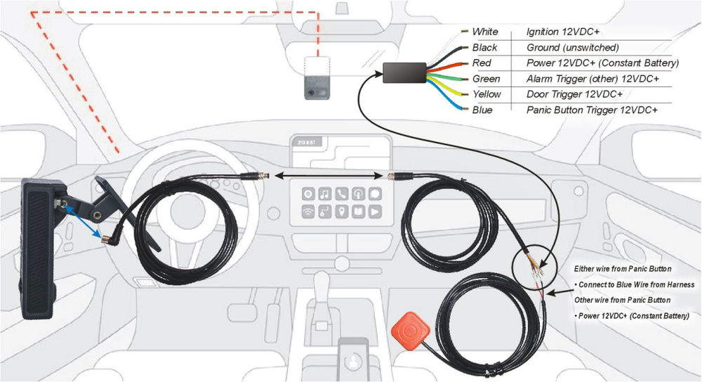
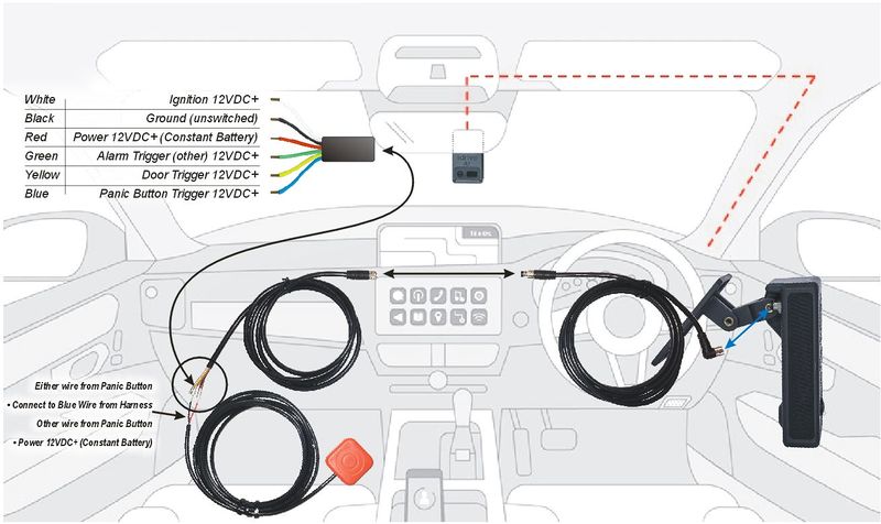
Required Connections
There are 3 required connections for the Idrive device to function properly.
- Connect the BLACK WIRE to battery negative or to a clean, metal vehicle GROUND.
- The RED power wire must be connected through the supplied fuse to a continuous 12VDC+ power source. This power source should never be cut off.
- It may be necessary to make a direct battery connection if your vehicle has a battery cut off or does not supply non-interrupted 12VDC+
- The WHITE ignition wire must be connected to a 12VDC+ power source that is ignition switched. This wire tells the camera to boot up or to enter transfer mode to download events.
- NOTE: Many vehicles trick you to thinking you have connected to an Ignition Wire, but after ignition off might not drop to 0VDC until the driver door opens and closes
- Avoid any of these ignition connections that are electronically delayed or conditionally switched with the driver's door
Optional Connections
There are 3 optional wire connections that will trigger an event on the Idrive device. The description of the usage shown is suggested however each wire may be connected to the trigger point of your choice so long as electrical parameters are met.
If you choose not to use the optional wires, verify that they are secured properly in order to prevent shorting.
- Connect the BLUE wire from the Camera to the Idrive Supplied Wired Panic Button (or trigger method of your choice). This wire requires a MOMENTARY 12V RISING edge level transition pulse of at least 50ms duration.
- Connect the GREEN wire to an Alarm circuit (or trigger method of your choice). This wire requires a 0V to 12V RISING edge level transition pulse of at least 50ms duration
- Connect the YELLOW wire to a Door circuit (or trigger method of your choice). This wire requires a constant 12VDC+ and triggers with a FALLING edge level transition pulse of at least 50ms duration
Test Cable Connections
IMPORTANT! Use a voltmeter to verify the proper connection of each wire prior to plugging into the Idrive device.
Plug the Circular Power Connector into the camera and screw it finger tight
- NOTES:
- The Circular Power Connector is keyed and will only insert into the camera exiting with the cable oriented upward
- Vehicle power above is stated as 12VDC+, and can be wired to a 24VDC+ vehicle electrical system
- IMPORTANT
- if you are using 12VDC+ for the RED Power Wire, make sure you are using 12VDC+ for the WHITE Ignition wire
- Likewise, if you are using 24VDC+ for the RED Power Wire, make sure you are using 24VDC+ for the WHITE Ignition wire
- Maintain similar voltage (12 or 24VDC+ respectfully) for Blue, Green and Yellow wires (if used)
- IMPORTANT
- NOTES:
IMPORTANT CABLE HARNESS NOTE
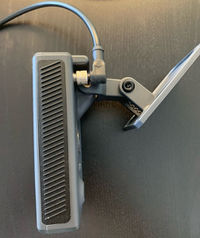
The AI Camera Wiring Harness features a Right-Angle power Connector; and when properly connected to the AI Camera
the cable will turn vertical/up and away from the Camera Toward the Roof of the vehicle.
After the cable is attached to the AI Camera, DO NOT ATTEMPT TO ROTATE the cable, it will Damage the connector.
It is not designed to move or rotate at all and any damage from this rotation is not covered under warranty.
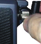
Other tips for safe, proper installation: Do not use any tools to tighten or loosen the locking ring on the connector, use only your fingers. Again, over tightening will damage the connector on the back of the AI Camera.
Note: Since the camera and the cabling is new, the fit is very snug.
You may need to tighten the connector ring until finger tight, then press the connector in a bit and repeat the process
with the ring until it is full seated with no threads showing at the bottom of the connector attached to the back of the AI Camera.
Accessory Installation
Wired Panic Button Installation
- Choose a secure and accessible location to mount the Wired Panic Button using use the pre-attached adhesive mounting tape
- After mounting the Wired Panic Button, route the cable safely toward the location that you terminated the cable harness to vehicle power connections.
- Securely connect one of the wires from Wired Panic Button to the blue wire from the idrive Power Harness using a butt connector.
- Connect the other wire from the Wired Panic Button to the same 12VDC location that you terminated the Red Battery Wire from the idrive device.
- Check that all connections are correct using a voltmeter
- Provide proper electrical insulation against short circuits using shrink tubing and/or electrical tape
- Suspend any unused cable out of reach and from possible abrasion with cable-ties or electrical tape
Notes:
- If more than one Wired Panic Button is to be installed, simply parallel the wires from the Panic Button to 12VDC power from each Wired Panic Button to the blue wire from the idrive Power Harness.
- If using an existing (X2 Wiring Harness and Panic Button) and connecting the AI Power Adapter cable to the X2 Wire Harness...
- the Panic Button wire will need to be changed from a Ground trigger through the Panic Button to a positive VDC trigger THROUGH the Panic Button
- the other side of the Panic Button does not change and remains connected to the Blue Wire on the wiring harness.
Idrive PowerUp2 Installation
- Mount the PowerUp to flat interior surface using double sided tape or zip ties attached to the Mounting wings.
- Carefully choose a location as it must remain within reach of the vehicle's power source and Power Harness.
NOTE: Please keep in mind that the PowerUp2 is not weather resistant!
- Connect the quick-connect Power Harness "Circular Power Connectors" from the "camera" to the PowerUp2 using the Male/Female connectors.
- You cannot connect the PowerUp2 backwards, as the connectors are keyed and match the connections for vehicle and camera connections.
- Install the fuse
If Adding to an Existing Installation
- Remove the Fuse currently powering the Idrive AI Camera
- Separate the Circular Power Connectors in the harness
- connect the PowerUp2 in the correct order to the Male/Female connectors in the harness
- Restore power with the Fuse
Uninstalling the Idrive AI device
- Depower the Idrive AI device by disconnecting the power harness from the vehicles power and ground (possibly just disconnect the fuse from the supplied fuse holder)
- Loosen the mounting screw and remove the AI Camera from the Mounting bracket
- Unplug the power cable from the camera by unscrewing the locking ring holding the circular power connector in the camera.
- In order to remove the mounting bracket from the windshield, carefully peel up the adhesive tape with a utility blade and soapy water (or a gentle solvent).
NOTES:
Do not remove the bracket if the device is sent in for RMA
Do not pull on the camera to remove the bracket from the windshield
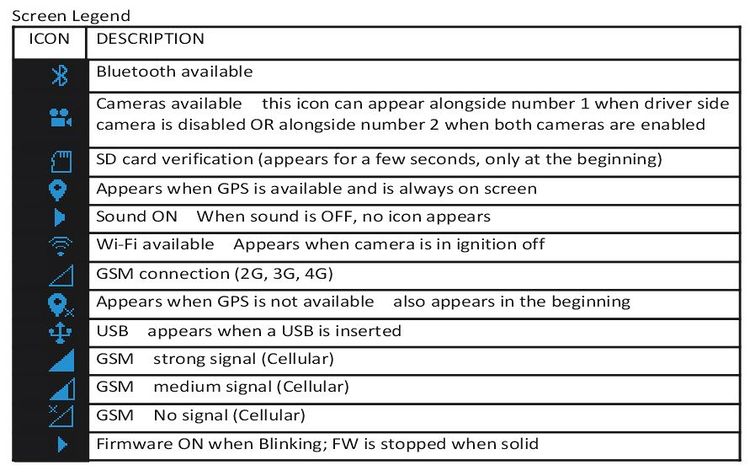
Idrive AI LCD Screen Icons / Mode Functionality
The Idrive AI has three major modes of operation: Event Monitoring Mode, Transfer Mode, and Sleep Mode.
System Icons
ON Screen Text Messages
- Yellow Wire - "Door"
- Blue Wire - "Panic"
- Green Wire - "Alarm"
- Shock
- Periodic
- Speed
- Live
- Safe Dist Warn
- Face Recogn
- Distraction
- Covered Camera
- Seatbelt
Error Messages
- E001 - SD Card issue (corrupted or missing SD Card)
- Camera can trigger events and upload the previews on Iris (with Cellular Subscription)
- However, if the connection with the server is down, the events are lost
- E002 - Improbable case when camera cannot load the settings from internal memory
- In this case the camera will work with its default settings and will have serial 111122223333
- The events are saved on SD Card, but the connections are rejected by CC / Node Server
- E003 - Camera does not receive GPS data from the GPS module
- Camera will include a generic GPS package at every one second
Event Monitoring Mode
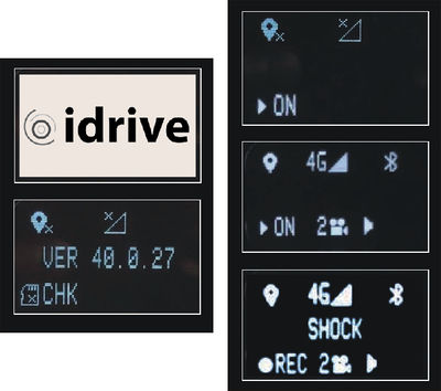
Upon ignition ON the AI will begin booting for approximately 120 seconds; Icons will be displayed in this order
after the Idrive Logo
- the camera checks the Firmware and storage
- checks and enables GPS and Cellular (if enabled)
- will then load the Roadside and Driver Side Cameras (if enabled)
After the initial booting phase LCD screen will Dim indicating that the camera is in Event Monitoring Mode and ready to record.
The AI will continually record for the duration of the ignition cycle. When an event is triggered, the device saves the footage leading up to the incident and the subsequent seconds afterward (The trigger being the midpoint). The AI indicates an event trigger by displaying Text Alerts (if enabled i the Control Center Software or via iris).
The AI is capable of the many types of Event triggers: However, immediately the AI Camera offers the most frequently used triggers...
- Shock Event - G-Force
The AI is built with internal accelerometers that will trigger when G-Force values are greater or equal to a threshold set in the Control Center software or through iris. The accelerometers are capable of trigger on 1-2 of 3 axes (forward, lateral, and vertical).
- Door Event - Yellow Wire Trigger
The AI Camera uses the existing circuitry of the vehicle to detect that a door has been opened. The download of door open events may be disabled in the Control Center. Door events that are not downloaded from the device will be deleted from the device after 3-7 days.
- Panic Event - Blue Wire trigger
Manually trigger an event by pressing the panic button.
- Alarm Event- Green Wire trigger
- Dependent on client wiring, the Green wire (Alarm Trigger) can be wired to a taximeter, dome light, Back Up Lights, etc.
Transfer Mode (WiFi or USB)
The Idrive device enters Transfer Mode when the vehicle’s ignition switch is turned OFF
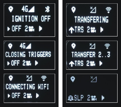
LCD screen displays text as follows:
- Ignition OFF
- Closing Triggers
- Connecting WiFi
- Transfering (if connected to WiFi)
The transfer of events to the idrive Base Station can be done with either the built in WiFi network (Default) or with the supplied USB-Micro Stick.
WiFi events transfer
The device will search for the idrive wireless network (LCD displays Connecting WiFi, and Transfering, see Text display images)
- The idrive device will attempt to make a connection 15 times over approximately 3.5 minutes
- When the idrive device is able to successfully connect to the idrive wireless network it will begin downloading all recorded events to the idrive Base Station
- Once all of the event data has been successfully transferred, or if a connection could not be established, the Idrive device will enter sleep mode (See Text display images).
USB Stick events transfer
NOTE: USB transferred events requires the idrive Base Station and Control Center Software to import events
- Make sure the Idrive device is booted and in Event Mode
- Insert the USB Micro stick into the USB connector ("D shape fits one direction)
- Make sure you wait 10 seconds prior to the turning ignition off
- USB transfer will begin and end with on screen text
- USB Transfer is completed once the Idrive device reaches Sleep Mode
- The camera will not search for the idrive wireless network while the USB is inserted.
(See the “Idrive Control Center Manual” for instructions on how to IMPORT the events into the Base Station with the USB stick)
Note: The USB Stick MUST HAVE your idrive.cert file on it to be authorized (this prevents unauthorized download of events)
WARNING: Do not unplug the idrive USB Stick during the transfer, as it may damage internal flash memory in the Idrive device or the USB Stick.
Sleep Mode
After the ignition is turned Off and the Transfer Mode is complete (either by WiFi or USB transfer) the idrive device will enter Sleep Mode (See Text display images above)
Sleep Mode length can be set on the idrive Base Station Control Center software or on the iris platform per device. The default sleep value is set to 30 minutes.
If an event takes place during Sleep Mode (e.g. Shock Event, Door Event, Panic Event, other Wire triggered Event) the text on the LCD screen will display SLP
- Once the timer has expired for Sleep Mode, the Idrive device will turn completely off and the screen will turn off
Understanding GPS
NOTE: On the very first use, the idrive AI unit must be outside of a garage for up to 10 minutes to acquire a line of sight GPS signal and become fully functional. The idrive device’s internal Date and Time are obtained from GPS. Vehicle speed is calculated by the GPS coordinates as are the mapping functions. Events may be recorded during this time without GPS information.
- GPS used for commercial purposes inherently has the average range error of more than 5 meters. Near buildings, underground, underpasses, or roadside trees, the range error may be more than 15 meters.
- For GPS to triangulate the location of the vehicle there must be signals received from 3 of the 4 satellites “visible” in the sky. (GPS is line of sight). It may take a short amount of time in the open for this to happen.
- When GPS satellite reception begins, this time may vary depending on weather and environmental conditions.
- Do not use GPS near other products that send electromagnetic waves or that use GPS. This may reduce the performance of the GPS reception in this product.
- Depending on GPS satellite reception, the accuracy of the mapping may not always show the shape of the road or a current location. Some examples of conditions that may affect GPS performance might include: Tall buildings, tree canopies, overpasses tunnels etc.
Electrical specifications
| AI Camera Specifications | |
|---|---|
| Input Power | 12-24 VDC Vehicles |
| Power Consumption | Nominal Range +250mA / +300mA - +500mA @12VDC
Sleep Mode (typically 30 min after ignition Off) less than +100mA @12VDC Power Off close to 0mA @12VDC |
| Voltage Spike Protection | Maximum input voltage operating range +38Vdc |
| WiFi Bands | 2400-2500MHz/5150-5850MHz |
| Bluetooth | Frequency use between 2.4GHz and 2.483GHz |
| Cellular | Frequency use between 698-2700MHz |
| Event Media | Internal-only SD Storage |
| Operating Temperature | Relative humidity 90% without condensation
Operation temperature range -10C° - +55°C° |
| Size and Weight | Size without Bracket - H: 120.2mm ~ 4.75”, W: 72mm ~ 2.875”, D: 43.5mm ~ 1.7” |
Electrical specifications PowerUp2
The below specifications are assuming an Idrive PowerUp2 is being used in circuit with the Idrive Camera
| PowerUp2 Specifications | |
|---|---|
| Input | 12-24 VDC Vehicles, Nominal Charging: 14.8 VDC for 12VDC, To Prevent Discharge
12-24 VDC Vehicles, Nominal Charging: 28.8 VDC for 24VDC, To Prevent Discharge |
| Output | LiPo (Lithium Polymer). Unlimited current consumption range +500mA -+700mA at 25 °C
Maximum current output (Battery powered) max. 1.67Adc for 60s paused 600s |
| Max Current | PowerUp is designed to support a single device. Maximum output voltage range (+12Vdc – +24Vdc) +15.6Vdc @ 1.67Adc. PowerUp2 is not designed to operate at Peak for prolonged periods of time and will decrease life |
| Back-Up Power | 12.5 VDC Nominal for connected Devices
X1P, X2, X2 V2 or AI Camera for minimum 20 minutes |
| LiPo Battery life | Min 1 year max 4 years (complete charge/discharge cycles reduces life expectancy) |
| Voltage Spike Protection | Maxim input voltage operating range +38Vdc
Automotive TVS for low dump protection (LDP01-42AY) +42Vdc |
| Operating Temperature | Relative humidity 90% without condensation
Operation temperature range -10C° - +55°C (NTC protection on) Storage temperature range -20C° - +70C° (without battery) Battery storage temperature -10C° - +55°C |
| Size and Weight | L: 5.5”, W: 3”, H: 1.75” |
