AI RMA Documentation:AI AI RMA and Programming Process
AI RMA Process
Receive RMA
Once the Support department has determined that RMA is necessary, they will fill in the form. (The Support team will mention in the form if there is any special action that needs to be taken before the repair starts)
The customer will be informed by the Support team of an estimated cost of repair(if the camera is outside of warranty) and if they agree the RMA process will begin.
The Support team will provide shipping instructions; upon receipt fill in the received date in the RMA form.
Once the shipment arrives, Support will notify the Repairs team. Information for each RMA request will be accessed from the Master RMA log file, which can be accessed here
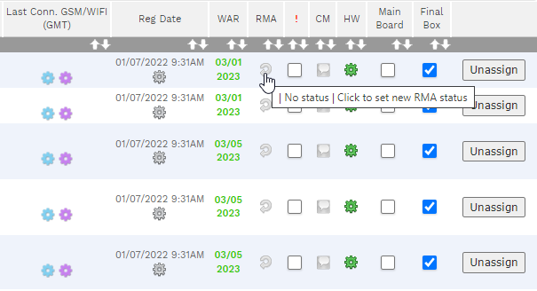
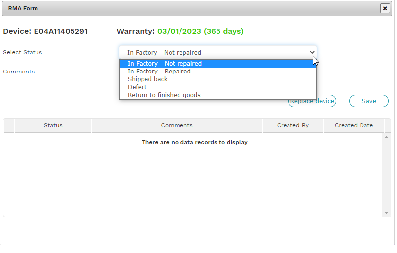
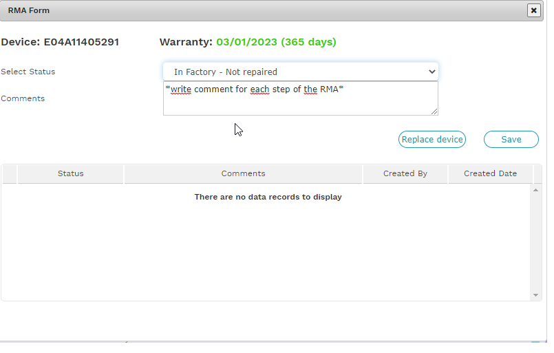
After each step of the RMA process, the Repairs team will need to update the RMA status in AC as seen below:
Inspect the AI Camera
Check general condition
Check the Power connector to see if it is broken (Check key position) If broken DO NOT PLUG IN THE CAMERA, go to disassembly.
Initial Test
Test the camera to verify reported issues.
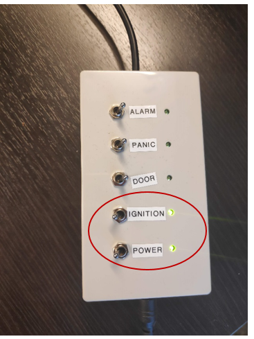
Determine if the AI is able to power on using the Idrive Ai Switch Box. If it does not power on, unplug from switch box and disassemble.
Note: When the USB cable is plugged into the camera but the power is not on, the AI will start to boot but fail in a loop. This is because the USB does not supply enough power to run the camera.
If the AI has previously had the power connector re-flowed you may not need to disassemble it. If it has not had this done then it will need to be disassembled to fix the connector.
Hardware issue Documentation
Determine if the Ai power connector is physically damaged. If it is make a note for out of warranty repair. see: AI Power Connector Reflow/Repair.
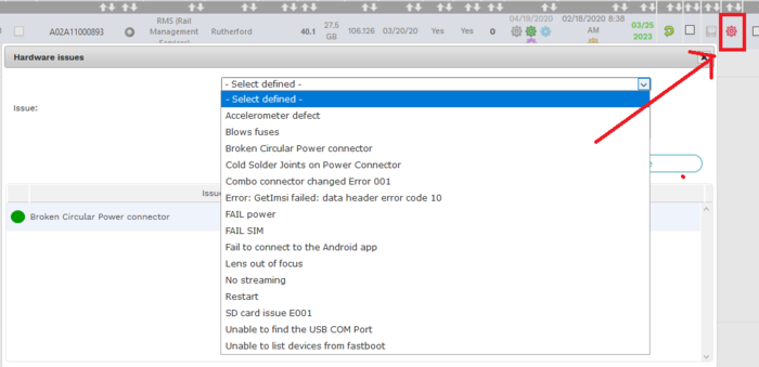
Document all issue in the Admin Center.
- Click the HW "Gear"
- Select Issue from the pulldown menu
- Once the issue is fixed click "Solved".
Disassembly
- Remove the 4 screws from the front of the case (TORX #6)
- Disconnect the 3 Coax cables from the main board.
- Do not pull directly up on the connectors or it can pull the connector off of the board!!
- Remove the cable but GENTLY prying up on the cable side of the connector and rock it up. (use the small pry tool)
- Remove the display board
- Remove the nut from the power connector (10mm on some 11mm on others, socket or wrench)
- lightly pry the board from the bottom and lift it out of the case
- Remove the speaker connector from the back of the board the connector pulls up and not in the direction of the wires
Before Programming
If the unit needs footage pulled from it, do this before anything else!
See: File Recovery with Android Studio
To pull footage connect Ai to Idrive Ai Switch Box and use a micro USB cable to connect the Ai to your desktop computer. (refer to Ai Power Loss Events section for now).
Programming
- Notes:
-Unlike previous Idrive X-series cameras, the Ai does not need to be disassembled to connect to factory tool. It will need to be disassembled if there are any internal issues.
-When a USB cable is plugged into the AI but power is turned off the camera will start to boot but continuously restart. This is because the USB does not supply enough power to fully run the camera.
Reassemble
- Make sure the speaker wire is not between the board and heatsink or the USB connector will not align in the plastics (and the heatsink will not be effective)
Final Testing
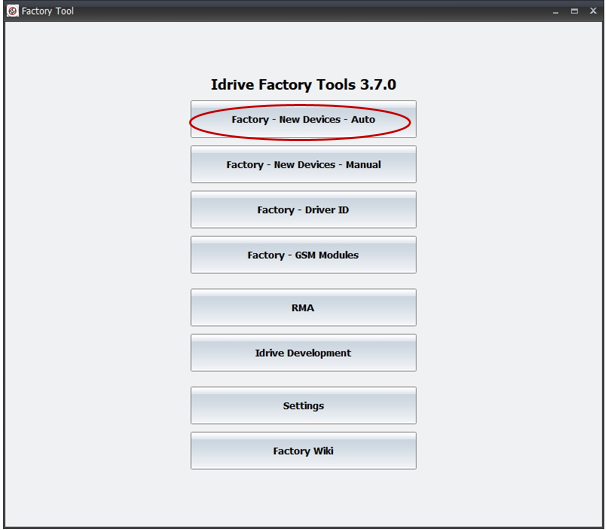
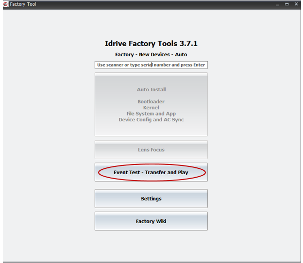
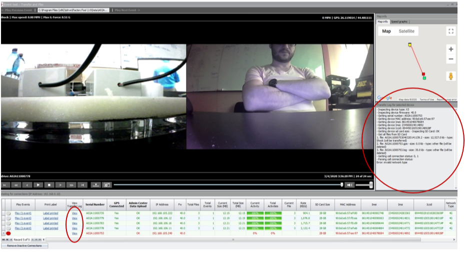
FINAL TEST (VIA FACTORY TOOL) 1. Open Factory Tool -> Factory - New devices – Auto -> Event Test – Transfer and Play (event test window will open – see at point 7)
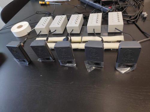
2. Connect 5 assembled AI cameras to Switch boxes power supplies (Power and Ignition are OFF).
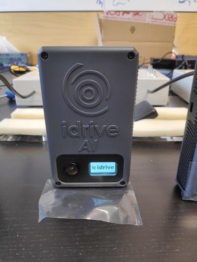
3. Switch Power and Ignition ON -> AI cameras will start to boot (Idrive logo will be displayed).
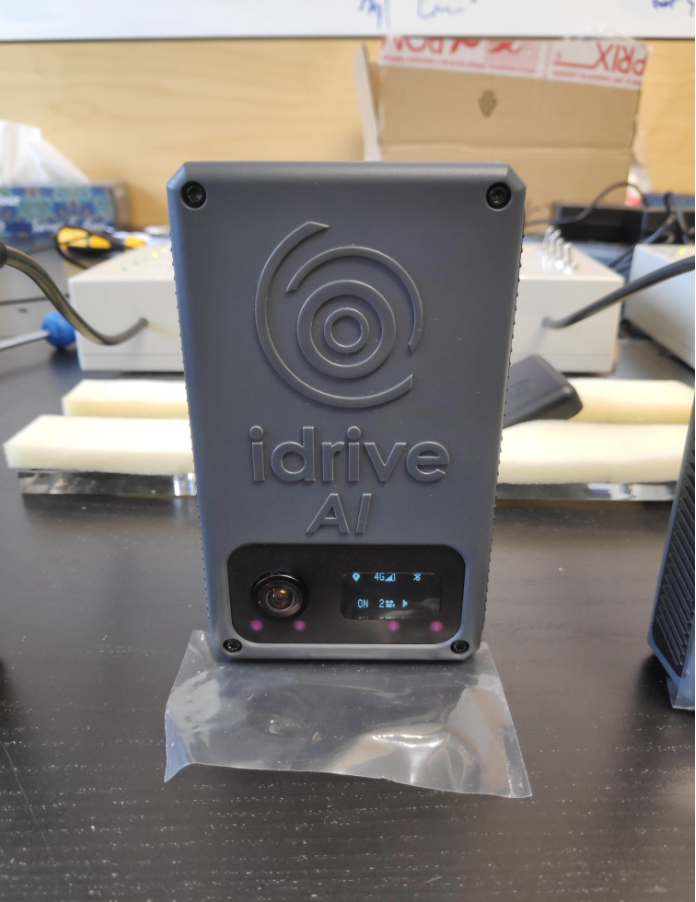
In this phase, AI cameras connect to GPS and to network (2G/3G/4G). The operator must pay attention to the cameras screens to assure that connections are available, and that all the icons are displayed and there is no error code. The Operator must test IR LED functionality by hovering a smartphone camera over the front of the device and see 4 separate lights – See picture below.
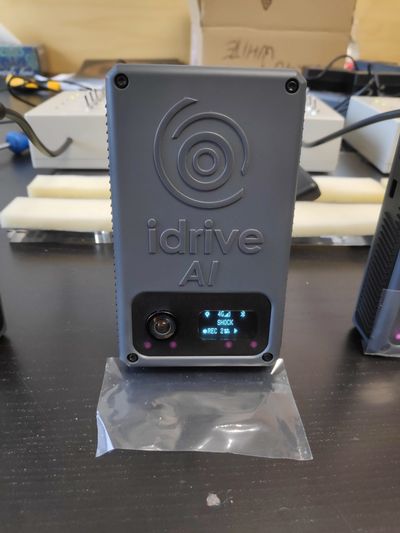
4. Trigger a SHOCK event by pulling (shaking) each AI camera backward and forward (once or twice)-> Message SHOCK will be displayed on the screen, moment when the camera starts recording the event.
5. After triggering and recording the SHOCK event (display gets back to normal), Switch Ignition OFF for AI cameras.
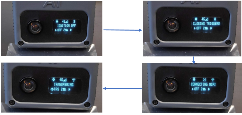
In this phase, AI cameras connect to Wi-Fi and start transferring. A text with IGNITION OFF followed by CLOSING TRIGGERS, by CONNECTING WIFI and by TRANSFERING along with specific icons, will be displayed on the screen.
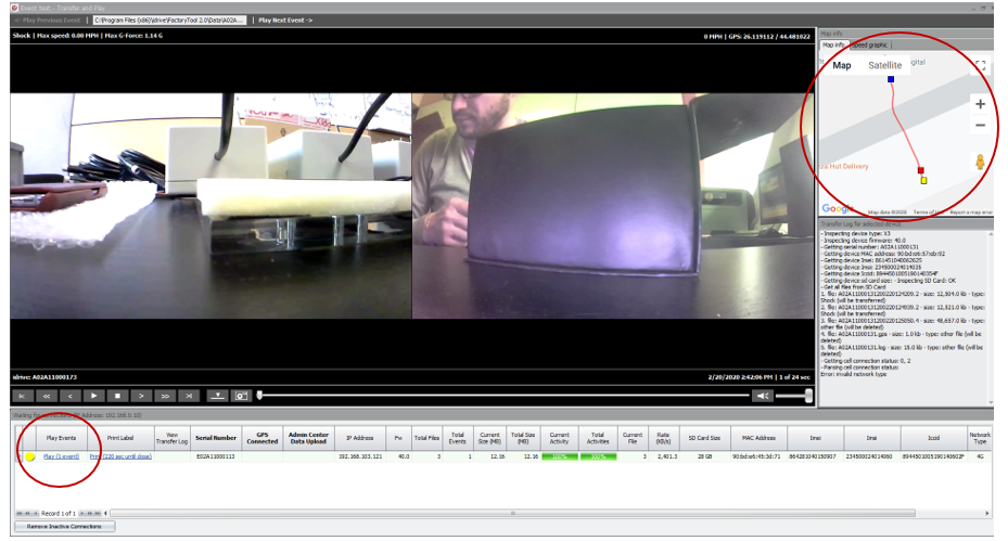
6. In the event test window, click on Play for each of the AI camera in the Play events area -> the record of the SHOCK event will be played.
Verify the focus of both lenses (image clarity). If the image is clear, lens focus was done properly. If not, the camera must be put aside. Check also if GPS route was recorded.
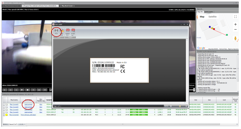
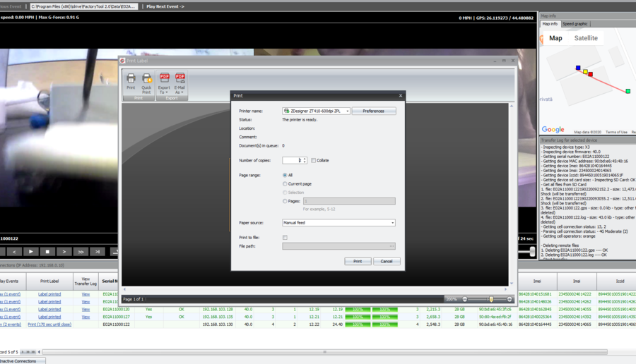
7. If lens focus OK and GPS route recorded -> Click on Label Printed – Print and print 2 labels. Close the window.
There will be displayed 2 messages: one for label print confirmation and one for beep confirmation.
If label was not printed, click NO and try again to reprint the label. Camera starts to beep only if label printed was confirmed. Once label print and beep confirmed, serial number text row turnes green. If there is no beep, it means that the camera has a problem with the speaker.
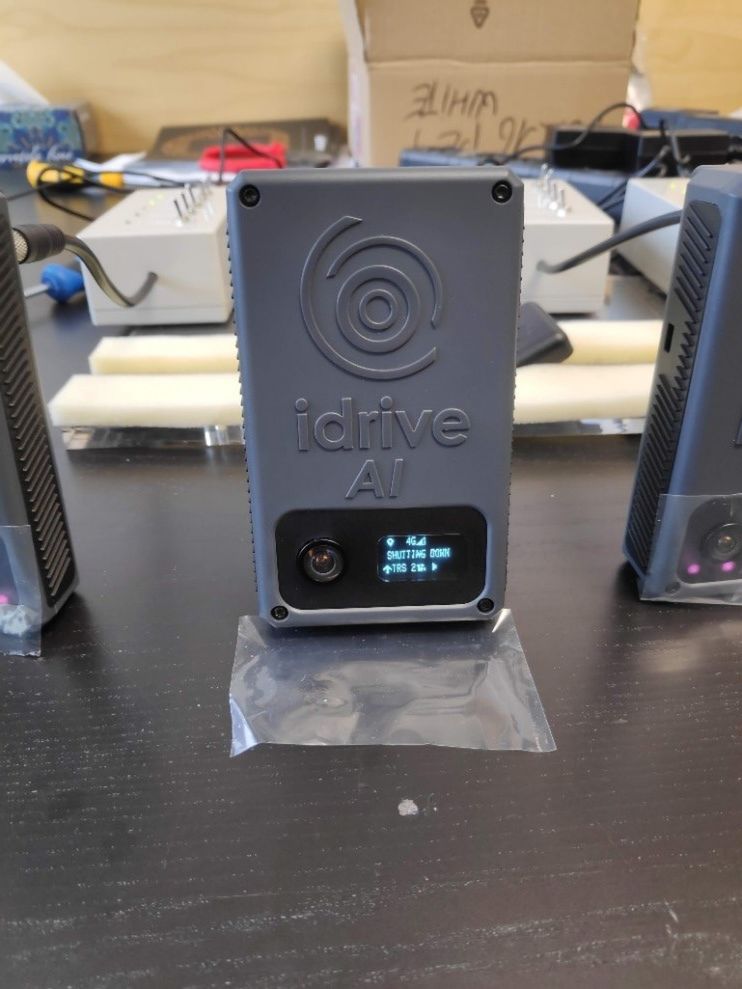
8. Camera will shut down automatically (SHUTTING DOWN message will be displayed) -> Switch Power OFF and Unplug the camera.
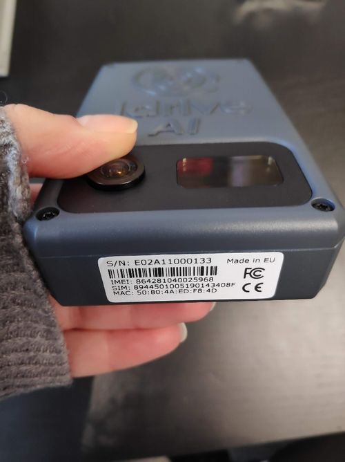
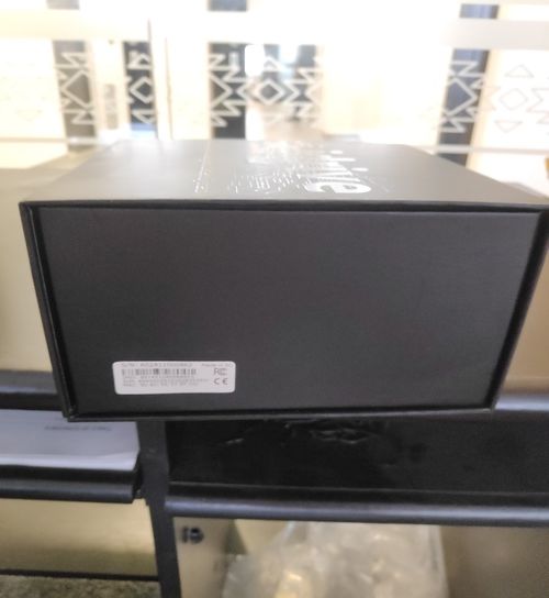
9. Apply one label on the bottom of the AI camera and one on the right side of the Final box.
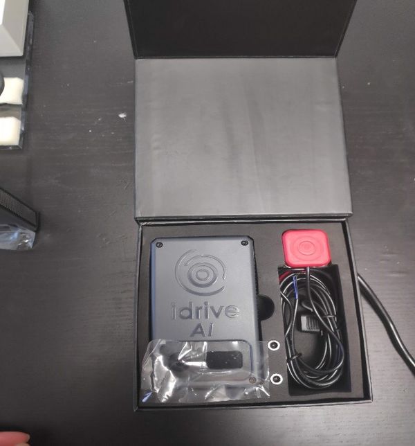
10. Put the AI camera into the Final box.
ISSUES:
- AI camera doesn’t boot (display is off): verify power circular connector if it’s properly soldered to the board.
If yes, AI camera has a problem with the display -> display needs to be replaced
If it’s not, manually redo the soldering of the connector.
- AI camera appear with red text in the event test window, click on View in the View Transfer Log and see what error occurred.
First, redo the final test (without another shock trigger). If camera didn’t pass second time either, try solutions below:
- Network error
verify if the 4G antenna connector is OK and properly inserted (visual inspection).
verify if the cable is properly soldered to the antenna.
If both above OK -> replace SIM card.
If one or both above are NOK, replace connector/replace cable/manually redo the soldering.
- GPS error
verify if the GPS antenna connector is OK and properly inserted (visual inspection)
verify if the cable is properly soldered to the antenna.
- Infinite loop = HW problem which requires a close HW verification.
- Lens focus NOK -> Disassemble the AI camera and replace entire gasket + lens holders + lens assembly.
- AI camera doesn’t beep = speaker problems -> verify if speaker connector is OK and if it’s properly inserted (visual inspection).
Final Docs
Every time progress is made with an RMA, the RMA form must be updated by the Repair team. Forms can be accessed directly from the Master RMA log found here.
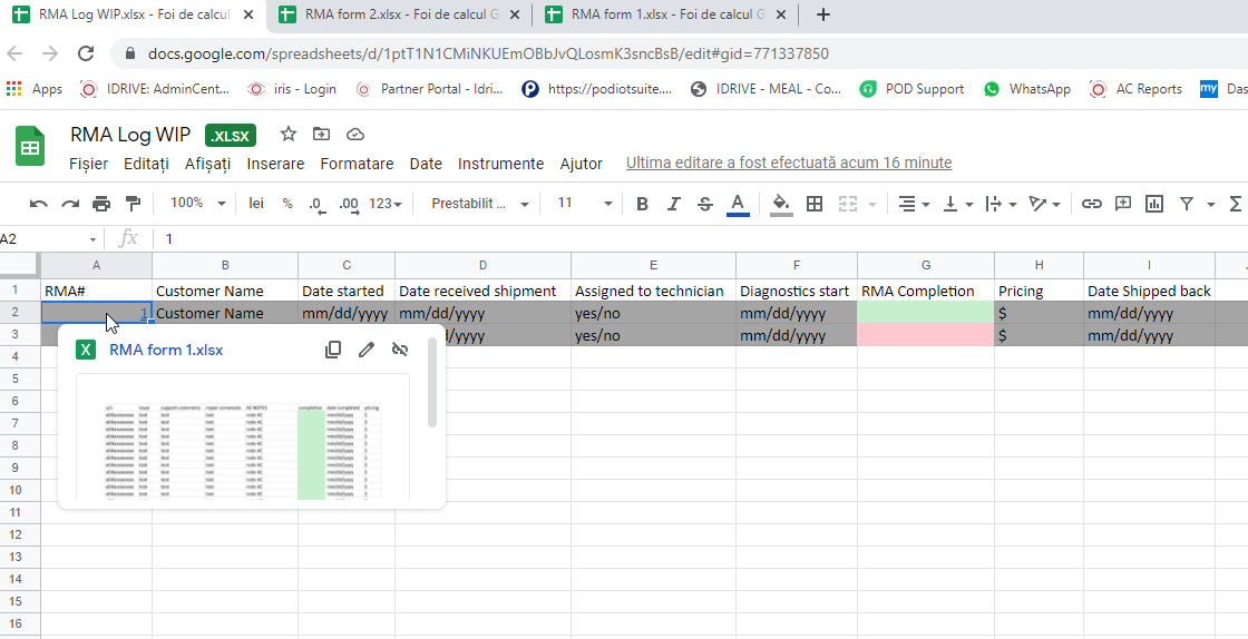
Once repairs have been completed from an RMA, the Master Log will also be updated accordingly.
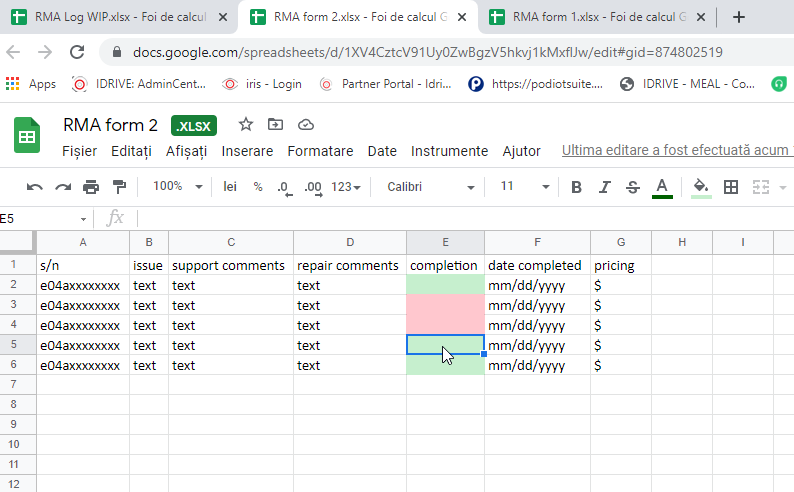
The final costs will be added and sent to the customer based on what was repaired.
Once the customer agrees to the costs, the shipment can be made.
