Safe Distance Warning
Concept Description
The main stept of how this feature works are:
1. SDW algorithm is scanning the road ahead and is detecting the locations of other cars
2. Due to the calibration procedure we are accurately detecting which of the detected cars are in a frontal position related to your car (on the same lane) and filter out cars placed on other lanes.
3. We approximate the distance to the closest car in front of you into 4 categories: extremely close frontal vehicle, close frontal vehicle, midrange frontal vehicle, far-mid range frontal vehicle.
4. Knowing your car current speed (from GPS) and distance to the closest car in front we can determine if you are keeping a safe distance to the car in front or not.
Trigger Conditions
Most of the data regarding speed and safe distance in the literature are highly exaggerated to be applied in a real traffic environment (most of them consider that the vehicle in front will suddenly freeze and calculate the distance that you have to keep considering your speed so that your braking time will be enough (driver reaction time + maximum braking distance). Also, there can be taken into account many car characteristics like cars mass, braking system, tire type, tire conditions, state of the road (icy, wet, dry, etc.). In the future we can implement a system that will use multiple parameters to calculate the speed- distance condition. Now we are using a trigger system based on real-life tests.
Calibration Procedure
The calibration procedure is mandatory (!!!) in order to have this feature available. Because the X2 camera can be mounted in any place on the windshield or even at different inclination angles and each car has its own characteristics (height, windshield inclination, windshield-front of the car distance, etc.), the designed algorithm will need to be calibrated to that specifically position of the camera mounted on car. After the calibration is done, the X2 camera should not be moved from that specific location and orientation. If the movement of the camera is necessary (RMA, moving the camera to another car, etc..) the calibration will need to be done again. Our calibration system allows us to do a very quickly and non-invasive calibration comparative with the other companies that are having this feature. Want we need for calibration is that the car that we want to be calibrated to be put between two traffic lanes (lanes width aprox 3.7 m (12 feet)). Considering that it will be a nightmare to put the cars in a road in order to calibrate them or to start drawing lanes in garages or parking lots, we are designing a roll-up carpet that is simulating the lanes. The only thing necessary is to unfold the roll-up carpet and put it in front of the vehicle, wherever the vehicle is placed. More details about this roll-up carpet will be given as soon as we will have some prototypes.
Calibration Interface
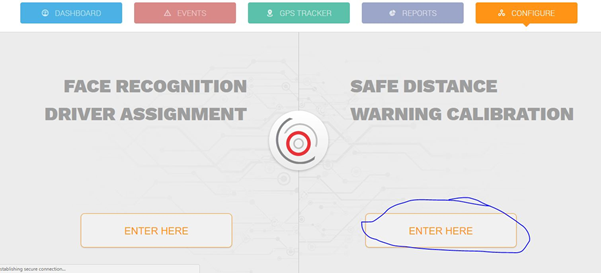
There are a few easy steps which need to be adhered to in order to successfully calibrate a device: 1. Open the Globalcenter 3 interface, on the Configure tab;
2. Click on the Safe Distance Warning Calibration ‘Enter here’ button;
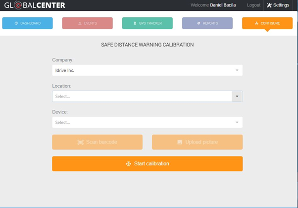
3.Select the location and the vehicle to be calibrated. Only compatible online vehicles will be shown in the list. (You can alternatively scan the barcode on the device or upload a picture of the barcode to identify the device – useful on mobile devices if the client has a lot of online devices);
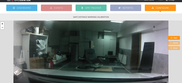
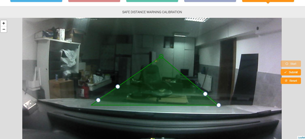
4. Click on ‘Start calibration’. A photo will be fetched real-time from the device, showing the guidelines (the image is from our calibration studio improvised in our garage, you can notice the 2 white lanes);
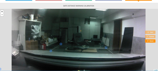
5. Click on ‘Start’ and place the calibration points as instructed (top and bottom of each visible line, they are 4 total points, the left lane first visible starting point (lower) and last point (upper) and the right lane first visible starting point(lower) and the last one (upper));
6. After placing the 4 interest points, the vanishing point triangle will be shown in green.
You can zoom in on the picture using the mouse wheel (or pinch-zoom on mobile) to adjust the position of the points.
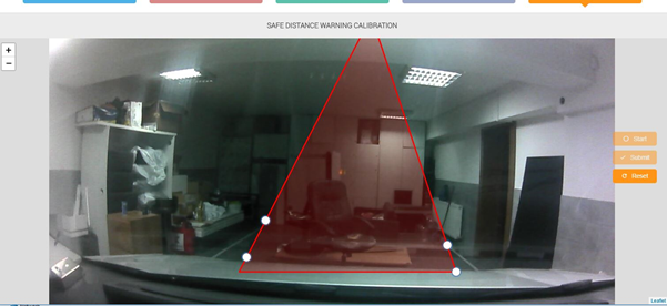
If there are errors, the triangle will be red and the submit button will be disabled.
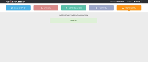
7. If the vanishing point triangle is green, a valid configuration can be sent to the device (via the ‘Submit’ button). Configuration will be sent and applied on the device in real-time.

