Manufacturing:Idrive X2 Programming Station Documentation
Revision as of 21:22, 20 July 2015 by Mark (talk | contribs) (Created page with "==Idrive X2 Programming Station Documentation == ===Programming Station Components=== thumb|400px| {| class="wikitable" |- !'''X2 Programming ...")
Idrive X2 Programming Station Documentation
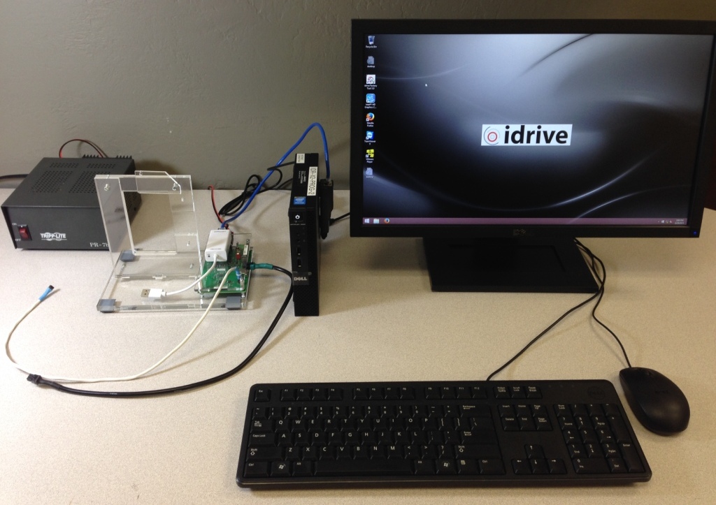
Programming Station Components
| X2 Programming Station Components |
|---|
| Windows 8 Computer with Monitor and speaker(s)(see requirements below) |
| Bar Code Scanner |
| Lens Focus Charts |
| Micro SD card reader |
| Idrive X2 Programmer Fixture |
| I/O Loopback Test Adapter |
| DC 12V/1A LINEAR power supply |
| USB type B cable |
| USB to Ethernet adapter |
| Cat5 Cable |
| Power cable for X2 |
| X2 Serial Programming cable |
<br\>
X2 Programming Computer Setup
Computer Hardware Minimum Requirements
- Monitor (needs to support 1600X1200 screen resolution)
- Speaker(s)
- Windows 8.1 Professional recommended
- 1GB RAM
- 100 GB Hard Disk
- 2 Network Interface adaptors (NICs)
- Keyboard and Mouse
Network Configuration
- Network Connection to the Programming Fixture
- IP address: 192.168.0.10
- Subnet Mask: 255.255.0.0
- Default gateway: Blank
- Network Connection with access to internet
- DHCP or as required by location
<br\>
Computer Software Requirements
- TeamViewer V9 (http://www.teamviewer.com ) - personal license. Install TeamViewer - during setup you need to choose the Personal license installation!
- Idrive Factory Tools 3.2.x
- Future Technologies USB Driver for X2 Programming Fixture (http://www.ftdichip.com/Drivers/VCP.htm)
- Firefox Web browser (https://www.mozilla.org/en-US/firefox/new/)
X2 Programming Fixture Setup
<br\><br\>
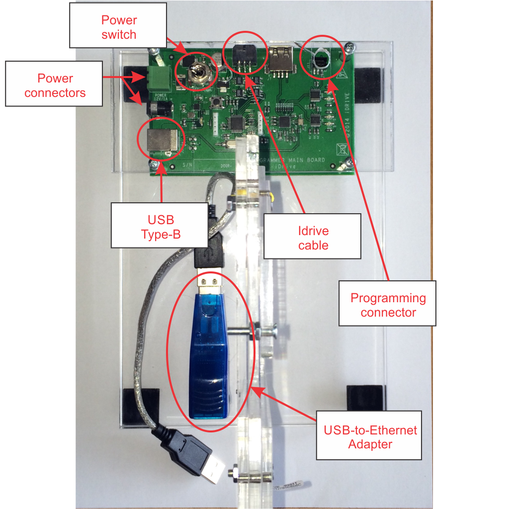
Computer Connections
- Connect the 12volt Power Supply to the Power Connector
- Connect the USB cable from Programming computer to USB Type B connector
- Connect the USB-to-Ethernet Adapter to the Programming Computer with a Cat5 (Network) Cable
Idrive Camera Connections
- Connect "Idrive Cable" to the Device to be programmed
- Connect the "Programming Connector" to the Device to be programmed
- Connect the USB-to-Ethernet Adapter to the Device to be programmed
<br\><br\><br\><br\>
Turn On the Power switch and leave the programmer on for the batch of boards.(you do not need to turn it off to program the next board)

