Manufacturing:X2 Secondary Configuration/Testing
Idrive X2 Configuration/Testing (Bi-Color LEDS, Accelerometers, IR LEDs, Wifi Transfers, GPS, labeling)
Note:The Idrive X2 programmer may also be used to perform this portion of the programming provided a wireless router is configured and connected to the system. For better throughput and to reduce the number of wireless networks in a factory environment it is recommended that the x6 Programmer be used. Because this document is intended to support production the x6 programmer process is shown here.
<br\><br\>
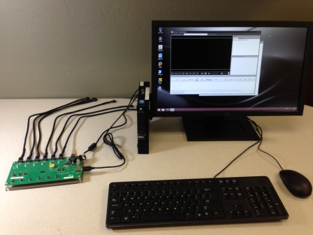
Idrive X2 Secondary/Final Test Station Setup
<br\><br\>
Stage 2 Initialize x6 programming station
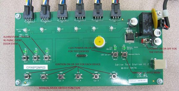
1. Connect up to 6 cameras into the x6 programmer using the 6 pin power cables
2. Turn on the power switch of the x6 programmer (applies power to the programmer)
<br\><br\>
Test X2 Internal Accelerometer function
1. After camera turns Green/Green shake each camera to trigger a shock event
- Right LED will turn red. Both LEDs green after event finishes recording.
<br\><br\>
Transfer the event(s) to the Test Station
1. Turn off the Ignition to the camera(s) and check Factory Tool verify that each camera downloads
- - Green text is good (verification that a shock event triggered and has GPS is present)
- - Red text is bad (Camera connected but no shock event was downloaded or failed GPS Data)
- - No text (camera did not download to test station. WiFi failure?)
<br\><br\>
Play and Evaluate downloaded event file(s)
- - Verify Both Driver and Road side images are clear and in focus
- - Verify that you can see the IR light reflected off of your hand
- - Verify audio sound clarity
<br\><br\>
Only after passing all test begin X2 Final Processing
Print and affix exterior serial number label to camera
from Radu, Turn into process doc: https://s3.amazonaws.com/tmp_idrive/factory_print_label_flow.mp4
- event(s) download via wifi to Factory tool
- review events
- if passed click on print label for that device
- - label with serial number, serial number bar code, wifi MAC address will print
- -the physical camera will flash for 400 seconds(default)
- - affix label over the case screw
- - click ? to label the next camera on the x6 test set
The default settings of the "Test Printer" window are matching with the physical labels that I used (width: ~25 millimeters, height: ~15 millimeters).
For a proper print, I had to change also the Top Adjustment to 2 mm from the Printer Properties and use the "Termal Direct" option (without ribbon).
As you can imagine, I cannot guarantee that these settings will match with the EMLinQ printers...
However combining the FT settings with the Printer Settings you can find the optimal configuration for any printer and label.
These FT settings are visible only in Dev mode (let me know if you need them available for everyone).
Printing labels is available on the Transfer Window. (firmware 21.6 or higher). After finishing the transfer, the FT will keep a 21.6 device alive (400 seconds - configurable from Dev Settings) An old device will be disconnected and the Print column will show a "N/A" text...
When you click on the Print link, the selected camera will start flashing (behind is a Wi-Fi command sent to the device and does NOT involve the X6). When the print window is closed, the FT will close the connection with the camera. You can click again on the link, but in this case you have to mannualy identify the camera (because the connection is closed).
I have not finished the FT yet, however I can provide you a temporary FT installer in a few days (and a 21.6 fw).
11. Print label containing the serial number, Bar code and MAC address and affix to the camera as shown:
10. Disconnect the power cable from the Camera(s)

