Idrive X2 Installation and Operation Guide
Copyright information
This document contains proprietary information that is protected by copyright. No part of this document may be photocopied, reproduced, or translated to another language without the prior written consent of Idrive Inc. Copyright © 2015 Idrive Inc.
This product incorporates copyright protection technology. Use of this copyright protection technology must be authorized by Idrive Inc. Reverse engineering or disassembly is prohibited. The information in this document is subject to change without notice.
Warnings
Please read the following carefully regarding proper use of the product and ensuring the user’s safety.
1. Use the idrive device only for its intended purpose.
2. Do not disassemble, attempt to repair, or alter the idrive device. When malfunctions, errors, or other damage is found to be attributable to a user, said user may not be eligible for after sale service.
3. When cleaning the inside of a vehicle, do not spray water or any other cleaning product directly onto the idrive device. It may cause damage, fire, or electric shock.
4. Keep the idrive device away from chemicals or detergents as they may change the surface of the product or ruin internal components.
5. Do not insert any foreign objects into the idrive device. Severe impact, shock, or other foreign matter may cause damage to the idrive device.
6. When foreign matter blocks the lens, normal operation is impossible. Always ensure that the lens is free of any contaminants or obstruction. Other objects placed around the camera may be reflected off of the window and included in the image, so please do not leave unnecessary objects around the idrive device.
7. The product will not operate properly if its position changes. Make sure the product is installed securely and do not expose the device to excessive shock. Do not move the device after installation.
8. Staring at or operating the product while driving is dangerous and may cause an accident.
9. Keep the product away from excessively humid or salty environments.
10. This product uses high definition cameras. Sudden changes in light levels, such as entering or exiting a tunnel, may result in temporary image quality degradation. Excessive or insufficient light may also degrade image quality.
11. Excessively tinted windshields may result in poorly defined or distorted images.
12. Use ONLY the supplied cable to connect the idrive device to the power source, and only as directed in the manual. This product should be connected only to the power inside a vehicle. Any other power source is unacceptable and may cause malfunction or fire and may render the idrive device ineligible for after sale service.
13. If power to the idrive device is lost (i.e due to an accident), an image may not be recorded.
Idrive X2 Basics
Accesories
Power Harness
Words here
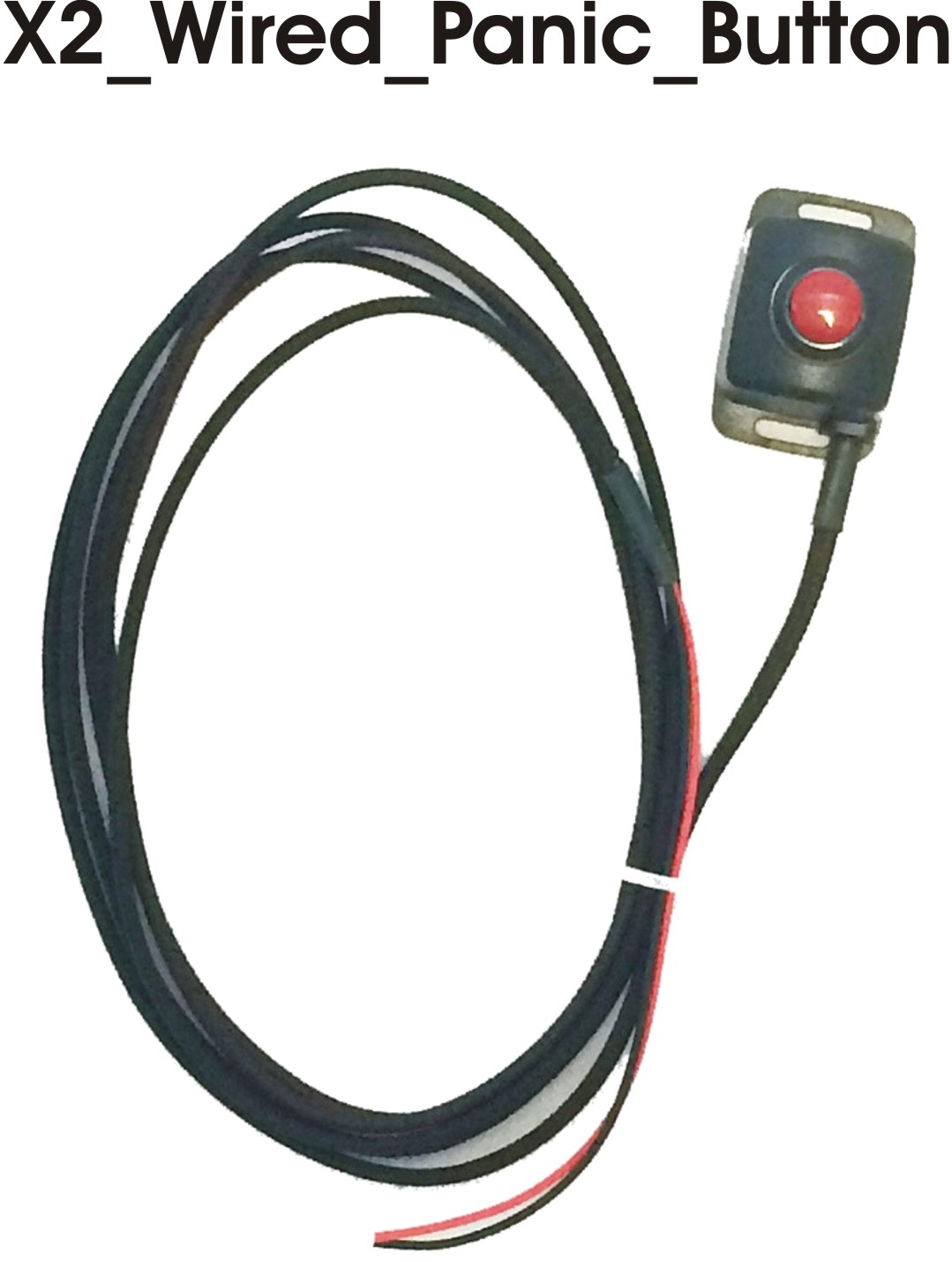
Wired Panic Button
Words here
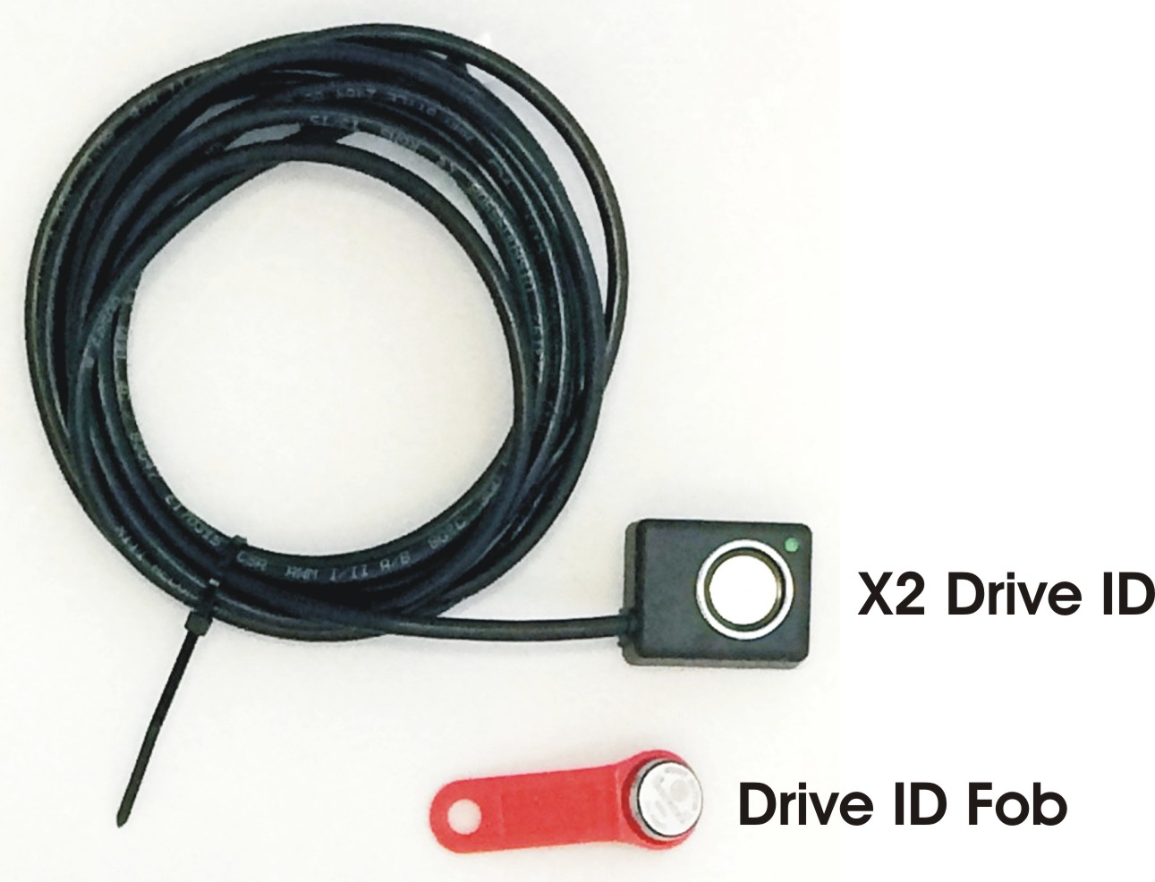
Driver ID
1) After you have installed the Idrive Camera in your vehicle, connect the Driver ID to the back of the camera using the Driver ID connector.
- a) Position the Driver ID in the vehicle cabin where it is easy to reach and it won’t affect the driver’s performance.
- b) Start your ignition
2) The LED will flash green after ignition and it will produce a beeping sound, letting the driver know it is ready to receive his/her Identity produced by their unique driver key.
- a) The driver should place his/her unique driver key into the circular slot on the Driver ID.
- b) The beeping and the LED flashing will automatically stop after the Driver ID has processed the Identity given by the unique driver key.
- i) Note: The Driver ID will continue beeping and the LED flashing bright green until the driver has connected his/her own unique driver key.
3) All the events that will be recorded on the camera will be assigned to the driver that has used his/her assigned unique driver key last.
4) If the drivers switch shifts and the ignition had not been turned off, the new driver can ID himself with his/her own unique key without having to turn the ignition off and on again.
- a) Note: If the new driver does not ID him/herself the Driver ID will continue using the identity from the previous driver.
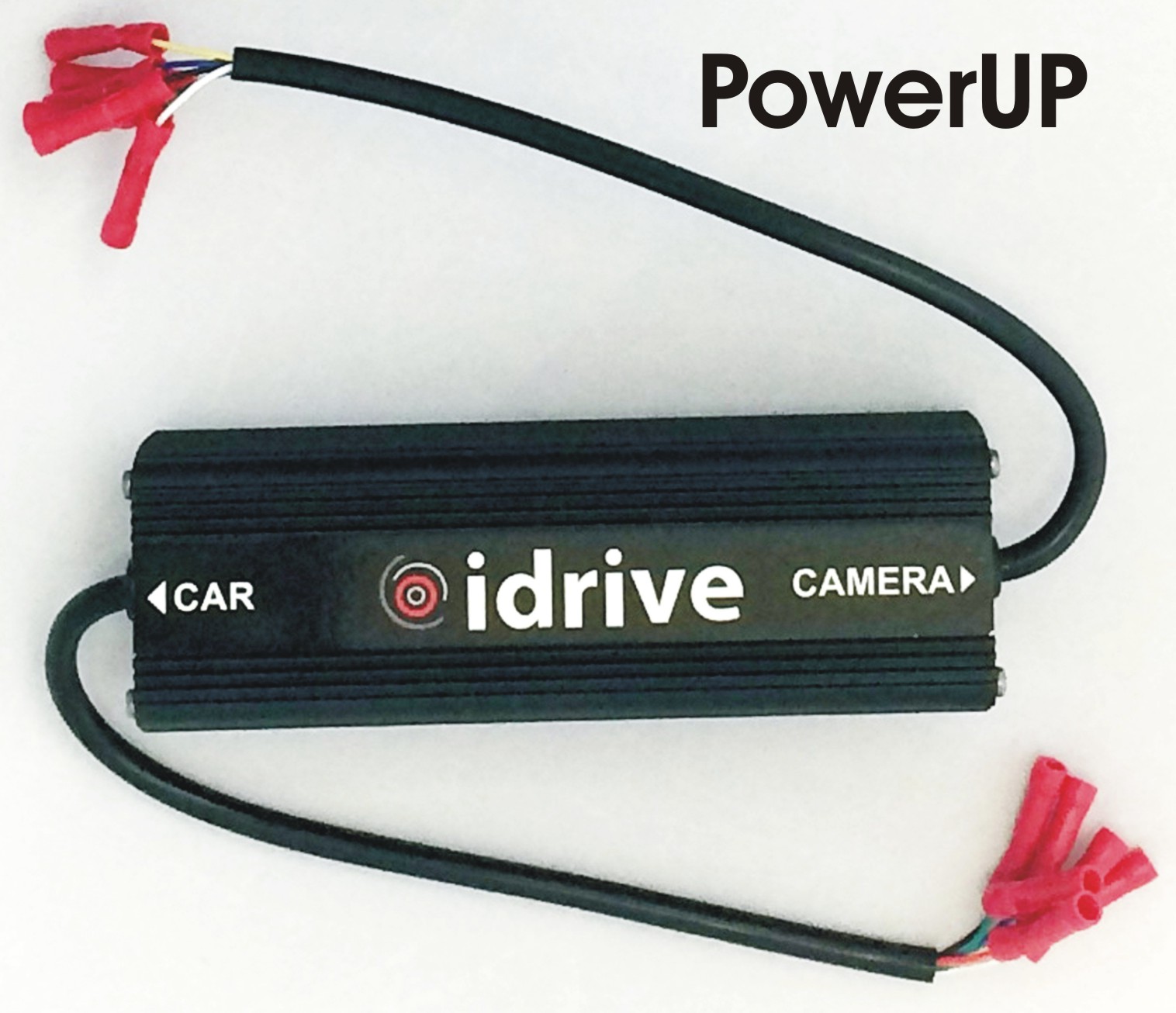
Idrive PowerUP
Words here
Idrive X2 Installation Instructions
Before you start
- Read this installation guide completely before beginning the installation.
- Ensure the idrive Base Station and wireless access point(s) are working. This is so you can test the camera installation and so the cameras do not fill up with events.
- Before installation, check the contents of the package and make sure all parts are accounted for and in good condition.
- Since part of the installation process is setting the angle of the device, it is important to choose a workspace where the vehicle is level and stable, and can remain so throughout the installation.
- Ensure that the mounting location chosen for the device will not interfere with the driver’s line of sight when operating the vehicle.
- Use the included installation hardware to make sure that the wiring for the system is secure, and will not interfere with the safe operation of the vehicle
NOTE: The idrive units should only be installed by a qualified technician.
Select the mounting location
The proper location for mounting the X2 device is on the top center of the windshield. Ensure that:
- Top center of the windshield
- Mount the camera vertically
- The lens must have an unobstructed view of the interior and the device must not interfere with the driver’s field of view.
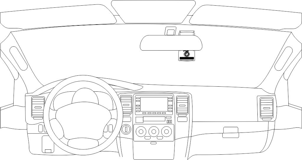 Correct Positioning
Permits clear view from the idrive device to the occupant cabin, unobstructed by the rear view mirror
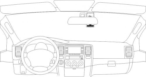 Too High
Blocks the driver and occupants faces showing eye and head positions during events
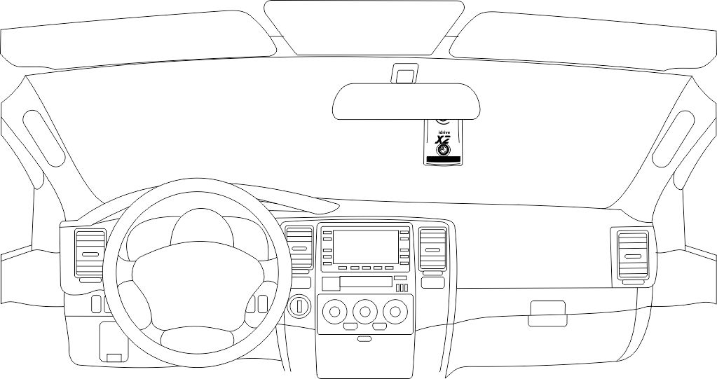 Too Low
Reduces cabin view and low hand placement during events. Also places forward viewing camera too low to the front hood reducing field of vision during events.
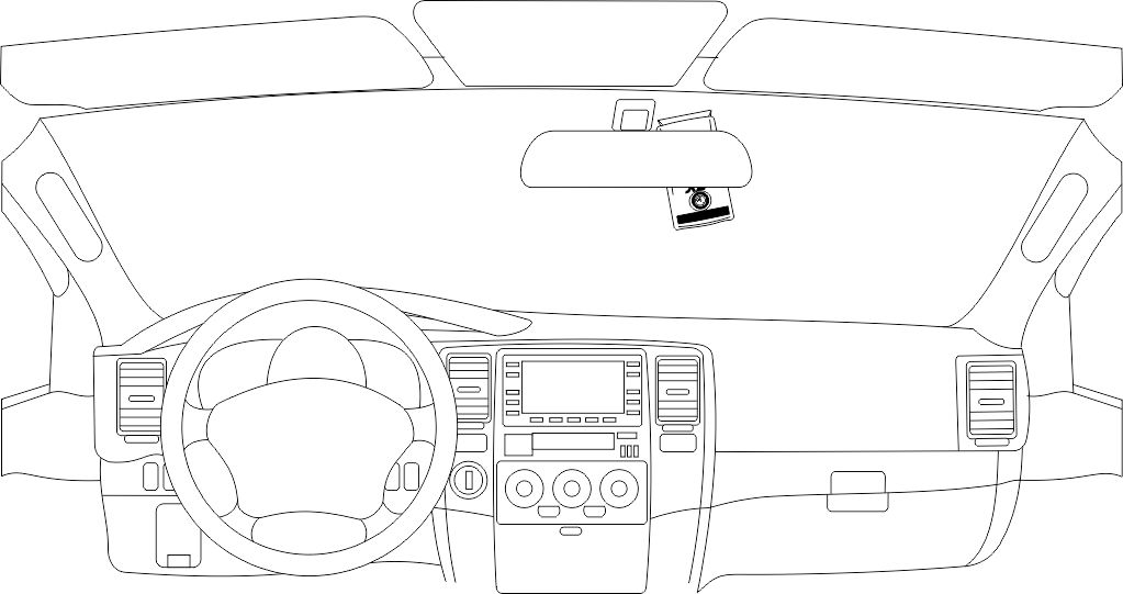 Wrong Angle
Obscures horizon for front viewing and cabin viewing cameras and reduces field of vision at outer edges of the event
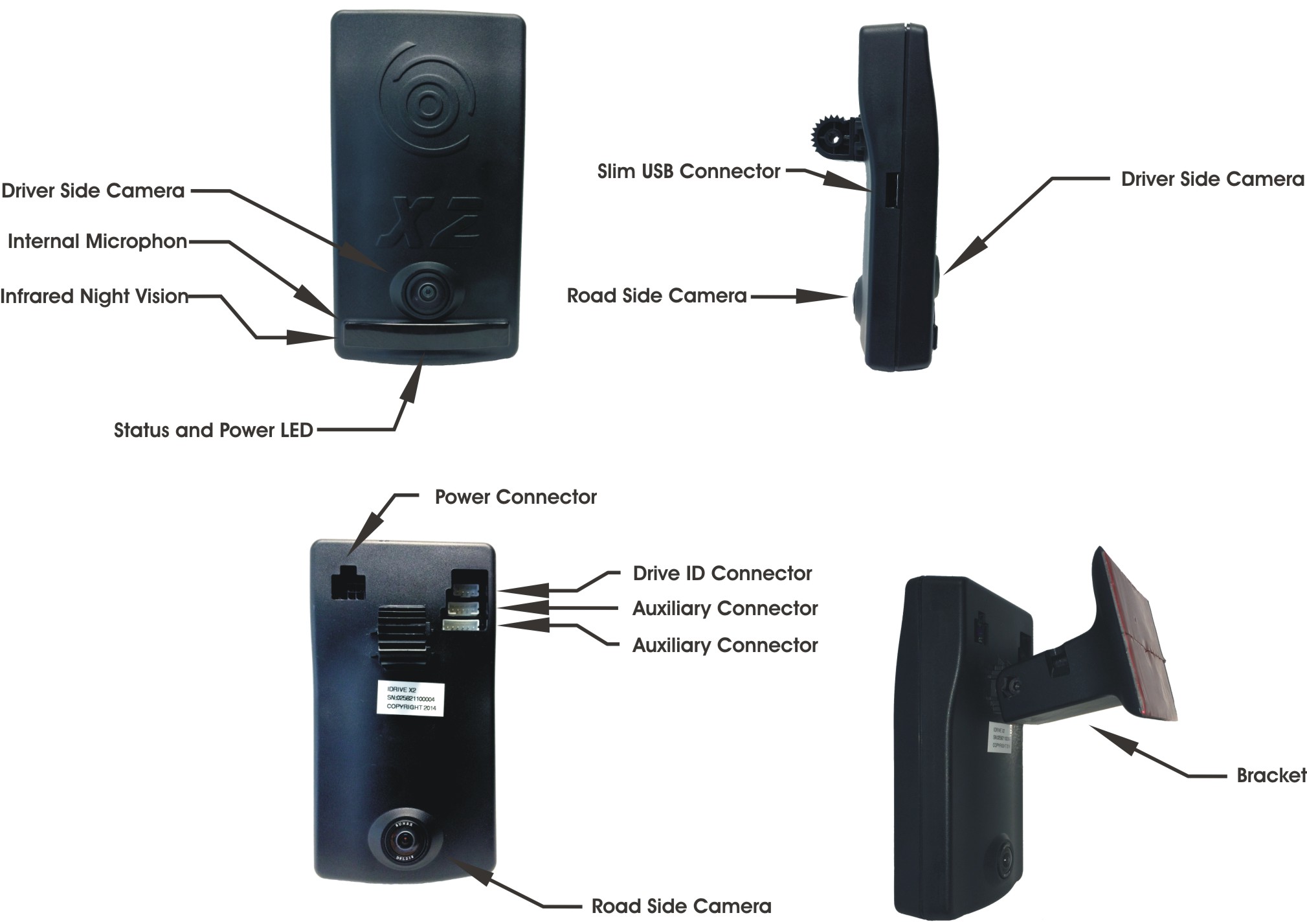
Mounting of the X2 Device
WARNING: The adhesive is very sticky. Once applied to the windshield, it will not come off easily. See page 21 for bracket removal instructions.
Install the mounting bracket
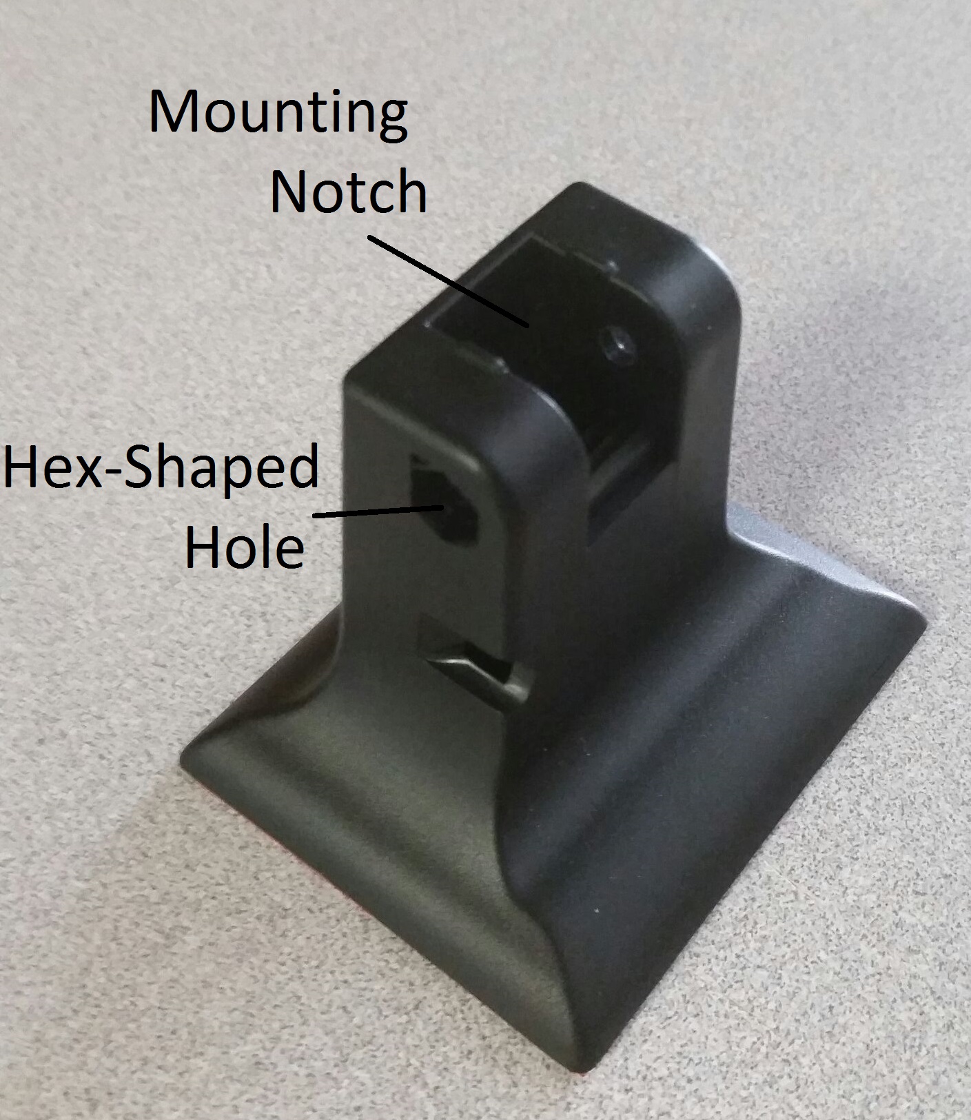
- Separate the X2 camera from the mounting bracket by removing the hex screw.
- Clean the installation area on the inside of the windshield using an alcohol wipe and wait until the windshield is completely dry. Make sure the glass is clean, dry and the air temperature is at least 50oF (10oC).
- Position the bracket with the mounting notch facing upward. Hold the X2 camera up to the bracket to confirm that the unit will hang vertically in the appropriate fashion in relation to the review mirror (as explained above). Mark this position with masking tape or a pencil.
- Remove the liner from the foam tape.
- Start by placing only the top edge of the bracket against the windshield, aligned with the guide marks.
- Press the bracket firmly against the windshield starting at the top and pressing the side downward. (Do not apply excessive pressure as it may cause the windshield to break)
- Make sure there are no large air bubbles under the bracket. You may need to (carefully) apply additional pressure to the bracket and remove any large air bubbles. Use a small pin to create an escape path for the air if the problem is persistent.
- Remove the tape, or markings using an alcohol wipe.
Install the X2 Camera into the bracket
- Insert the nut into one of the hex-shaped holes in the bracket and hold it inside with a finger. Verify the nut fits flush with the hole, and is not sitting at an angle.
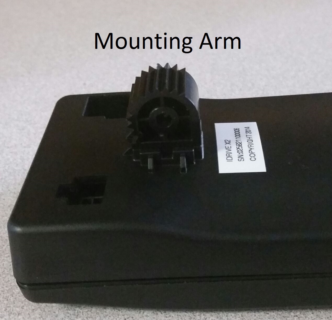
- Align the mounting arm and notch on the camera and bracket, respectively, so that the camera hangs vertically.
- Insert the bolt into the opposite hex-shaped hole as the nut, and turn until tight. As long as you hold the nut inside with a finger, it should catch and turn down to the bottom.
- NOTE: once the bolt is inserted, the camera's position is rigid. The bolt must be removed completely if the position is to be altered.
Route the Idrive X2 Power Cable
WARNING: When installing the Idrive X2 Cable in a vehicle with side or curtain airbags, be certain that neither the cable nor your installation activities interfere with any airbag related mechanisms or might otherwise affect airbag deployment.
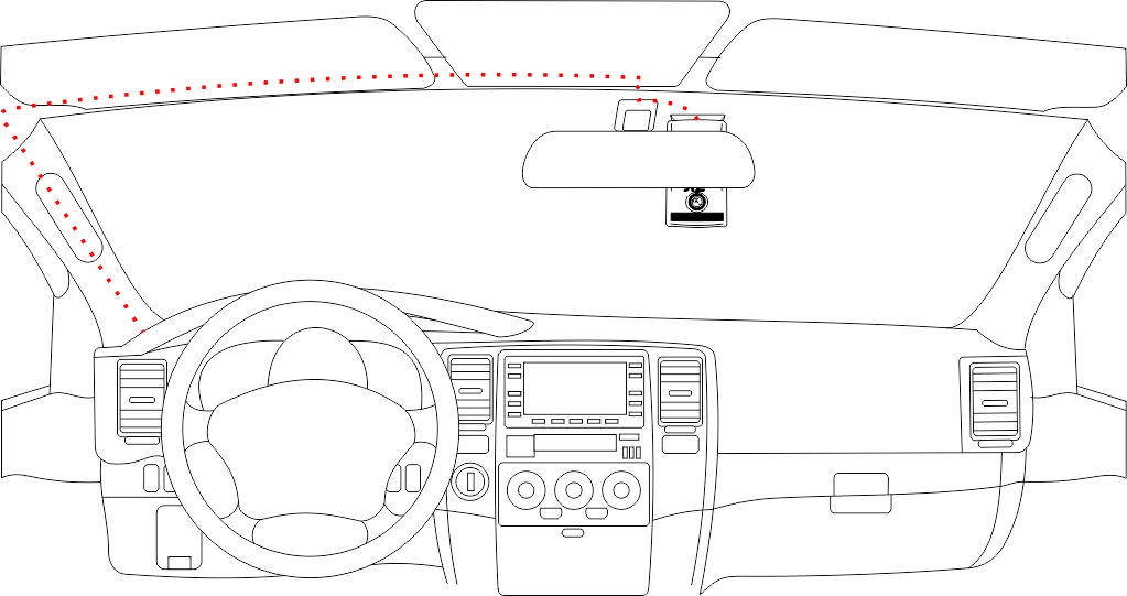
Starting just above the rear view mirror, route the cable under the window trim or headliner across to the door pillar.
Route the cable down the door pillar underneath the vertical door / window trim.
Route the cable out from underneath the trim and under the dashboard.
Note: You may need to remove the trim to route the cable. When reinstalling, be careful not to damage the trim clips or the cable. Keep the cable away from sharp edges and moving parts.
Route the Idrive X2 Driver ID Cable
Starting just above the rear view mirror, route the cable under the window trim or headliner across to the door pillar.
Route the cable down the door pillar underneath the vertical door / window trim.
Route the cable out from underneath the trim and affix the Button to the dashboard using the double sided tape.
Idrive X2 Wiring Diagram
The Idrive X2 Cable is 14 feet long with a 6PIN connector at one end. One end of the cable - the 6PIN connector- plugs into the idrive device. It is then routed and secured under the dashboard.
The routing of the power cable will vary greatly depending on vehicle type. Choose a routing that will work the best for your particular application.
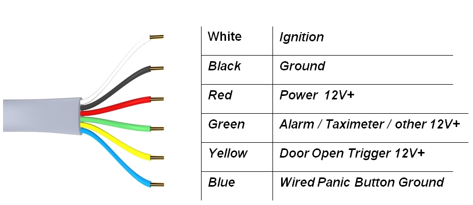
Attach the wires to the sources in the vehicle as shown below:
Required Connections
There are 3 required connections for the idrive device to function properly.
- Connect the BLACK WIRE to negative or to a clean GROUND.
- The RED power wire must be connected through the supplied fuse to a continuous +12V power source. This power must never shut off for proper device function.
- The WHITE ignition wire must be connected through the supplied fuse to a 12V power source that is ignition switched. This wire tells the camera to boot up or to enter transfer mode to download events.
Optional Connections
There are 3 optional wire connections which when properly connected, will trigger an event on the idrive device. The description of the usage shown is suggested however each wire may be connected to the trigger point of your choice so long as electrical parameters are met. If you chose not to use the optional wires ensure that they are secured properly to prevent shorting.
- Connect the GREEN wire to an Alarm Button (or trigger method of your choice).(This wire requires a 0V to 12V RISING edge level transition pulse of at least 50ms duration)
- Connect the YELLOW wire to a Door Open (or trigger method of your choice).(This wire requires a 0V to 12V FALLING edge level transition pulse of at least 50ms duration)
- Connect the BLUE wire to a Wired Panic Button (or trigger method of your choice). (This wire requires a MOMENTARY 0V FALLING edge level transition pulse of at least 50ms duration.) e.g. a momentary ground through the wired panic button.
Test Cable Connections
IMPORTANT! Use a voltmeter to verify the proper connection of each wire prior to plugging in the idrive device.
Plug the cable into the Device
Idrive X2 Functionality Modes and LED Behavior
The idrive X2 device has three major modes of operation:
Event Monitoring Mode
Initially after ignition energizing, the idrive device will display (Red/Green LEDs) for approximately 30 seconds during initialization. The Event Monitoring Mode will then start when the camera is fully initialized
(Green/Green LEDs)
- The idrive device will be continually recording but not saving data
- When an event occurs the device will save data to internal memory
- Starting from a time interval prior to the event trigger
- Ending at a time interval after the event trigger
- The time interval is set in the idrive Control Center
- If set in the Control Center, the idrive device will display a Left RED Event LED(Red/Green LEDs) for the duration of that event.
Transfer Mode (WiFi or USB)
The idrive device enters Transfer Mode when the vehicle’s ignition switch is turned OFF 50px(Amber/Green LEDs).
The transfer of events to the idrive Base Station can be done with either the built in WiFi network (Default) or with the supplied mini-USB Stick.
Wifi events transfer
The device will search for the idrive wireless network 120px(Flashing Amber/ Solid Green LEDs)
- The idrive device will attempt to make a connection 15 times over approximately 3.5 minutes
- When the idrive device is able to successfully connect to the idrive wireless network 50px(Solid Amber/Solid Green LEDs) it will begin downloading all recorded events to the idrive Base Station
- Once all of the event data has been successfully transferred, the idrive device will shut 50px off (Both LEDs Off)
OR
- If it cannot connect within that time period the idrive device will shut off 50px (Both LEDs Off)
OR
- If set in the Control Center, The X1 device will record events after the ignition is turned OFF.
- Left LED Off and the Right LED will remain steady Green 60px (Off/Green)(See Sleep Mode Below)
USB Stick events transfer
Two methods to insert the USB properly Ignition ON or Ignition OFF
Ignition ON
- Make sure the LEDs are Green Green
- Insert the USB stick into the left side of the camera having the gold fingers on the USB stick facing away from you
- Make sure you wait more than 60 seconds prior to the ignition switch being turned off
- USB transfer will begin 50px(Solid Amber/Solid Green LEDs)
- The camera will not search for the idrive wireless network
OR
Ignition OFF
- Make sure the LEDs are OFF Green or OFF OFF
- Insert the USB stick into the left side of the camera having the gold fingers on the USB stick facing away from you
- Turn the Ignition ON and let the Camera Boot up to Green Green
- Wait 30 seconds and turn the Ignition OFF
- USB transfer will begin 50px(Solid Amber/Solid Green LEDs)
- The camera will not search for the idrive wireless network
Note: The USB Stick MUST HAVE your idrive.cert file on it to be authorized (this prevents unauthorized download of events)
Note: The USB stick MUST NOT be removed prior to transfer completion or data loss may occur
- Completion is indicated by both LEDs being Off 50px (See the “idrive Control Center Manual” for instructions on how to IMPORT the events into the Base Station with the USB stick)
OR
- If set in the Control Center, The X1 device will record events after the ignition is turned OFF.
- Left LED Off and the Right LED will remain steady Green 60px (Off/Green)(See Sleep Mode Below)
WARNING: Do not unplug the idrive USB Stick during the transfer 50px(Solid Amber/Solid Green), as it may damage internal flash memory in the idrive device or the USB Stick.
Sleep Mode
After the ignition is turned Off and the Transfer Mode is complete (either WiFi or USB) the Left Red LED will flash (OFF-ON-OFF) and the Right LED will remain steady Green 60px (Off/Green)
This device is now in Sleep Mode. The duration of Sleep Mode (before turning off) is set in the Control Center per device.
During Sleep Mode, if an event takes place that is enabled for a specific Device (e.g. Shock Event, Door Event, Panic Event, other Wire Event) the left LED will turn RED, and the Right LED will remain Green for the duration of the Event as set in the Control Panel for that device.
- Once the timer has expired for Sleep Mode, the idrive device will turn both LEDs Off 50px
Idrive Event Types
G-Force (Shock) Event
By default the idrive device will save video from 8 seconds before the event to 8 seconds after the event trigger (16 seconds total). (G-Force levels and default event lengths can be changed in the idrive Control Center.)
Door Open Event
When a door is opened, the idrive device will record from 5 seconds before the event to 5 seconds after the event (10 seconds total). The idrive device uses the existing circuitry of the automobile to detect that the door has been opened. The download of door open events may be disabled in the control center. Door events that are not downloaded from the device will be deleted from the device after 3 days.
Wireless Panic Event
By default when the wireless panic button is pressed, the device will save 15 seconds prior to and 15 seconds after the event trigger. (The default event lengths can be changed in the idrive Control Center.)
Wired Panic Event
By default when a wired panic button is pressed, the idrive device will save from 15 seconds before the event to 15 seconds after the event trigger. (The default event lengths can be changed in the idrive Control Center.)
Alarm Event
By default when the wireless panic button is pressed, the idrive device will save from 15 seconds before the event to 15 seconds after the event trigger. (The default event lengths can be changed in the idrive Control Center.)
The video together with the G-Force values, the GPS coordinates, date and time form an “Idrive Event File”. The Event File is saved on an internal flash memory.
Basic LED behavior
Understanding GPS
NOTE: On the very first use, the idrive X2 unit must be outside of a garage for up to 10 minutes to acquire a line of sight GPS signal and become fully functional. The idrive device’s internal Date and Time are obtained from GPS. Vehicle speed is calculated by the GPS coordinates as are the mapping functions. Events will record during this time without GPS information.
- GPS used for commercial purposes inherently has the average range error of more than 5 meters. Near buildings, underground, underpasses, or roadside trees, the range error may be more than 15 meters.
- For GPS to triangulate the location of the vehicle there must be signals received from 3 of the 4 satellites “visible” in the sky. (GPS is line of sight). It can take some time in the open for this to happen.
- A certain amount of time is needed from when the engine of a vehicle is started until GPS satellite reception begins, and this time may vary depending on weather and environmental conditions.
- Do not use GPS with other products that send electromagnetic waves or that use GPS. This may reduce the performance of the GPS reception in this product.
- Depending on GPS satellite reception, the accuracy of the mapping may not always show the shape of the road or a current location. Some examples of conditions that may affect GPS performance might include: Tall buildings, tree canopies, overpasses tunnels etc.
Uninstalling a device
- Unplug the power cable (Insert a pin into the hole on top of the device above the 6 pin power connector. Press in with the pin and carefully pull the cable out).
- Remove the GPS Pod from the windshield. (X1 Models had an external GPS puck, the X1-P and X2 utilizes an internal GPS)
- Unscrew the fastener from the bracket end of the mounting arm.
- Remove the bracket from the windshield – use a label-off product and carefully pull the bracket from the windshield. Note: If you are returning the device for repair or replacement, skip this step.
Wired Panic Button Setup
If you have chosen to install the Wired Panic Button as an option to your idrive device installation, please follow the instructions below:
- Choose the location to mount the Wired Panic Button carefully
- Listed below are just a few scenarios when the location for the wired Panic Button:
- Is the location for driver access within or outside of visual range
- Is the location for driver access within or outside of arms reach
- Is the location potentially hazardous to safe vehicle operation
- If hidden, (e.g. in a glove box or under a seat) accidental activation may occur due to movement of clip boards or miscellaneous in-cab utilities
- An exposed Panic Button may call to much attention to itself
- If surface mounted, you have the option to route the wiring to exit through the side or the back of the Wired Panic Button housing
- You may wish to install more than one Wired Panic Button (wired in parallel)
- After mounting the Wired Panic Button, route the cable safely toward the location that you terminated the cable harness from the idrive device
- Connect the Black wire from the Wired Panic Button to the same ground location that you terminated the Black Ground wire from the idrive device
- Securely connect the Red wire from Wired Panic Button to the Blue wire from the idrive Camera harness using either a wire nut, solder, or other wire connector
- Check that all connections are correct using a voltmeter
- Provide proper electrical insulation against short circuits using shrink tubing and/or electrical tape
- Suspend any unused cable out of reach and from possible abrasion with cable-ties or electrical tape
Note: if more than one Wired Panic Button is to be installed, simply parallel all Black wires from the Panic button to ground and parallel all Red wires from each Wired Panic Button to the Blue wire on the idrive Camera Harness as in items 3 and 4
