X1 V7 series Main Board Manufacturing and Programming
Copyright Information
This document contains proprietary information that is protected by copyright. No part of this document may be photocopied, reproduced, or translated to another language without the prior written consent of Idrive Inc.
About This Document
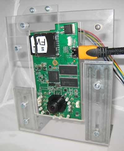
This document contains the information necessary to produce a fully programmed Idrive Main board suitable for building of an Idrive X1 V7 series camera. This includes all programming, testing, focus of lenses and bar code label.
Build Lot Preparation
Purchase all required parts.
Supplied serialized Bar code Labels from idrive, one per board.I propose we buy preprinted Polyimide lables for the main board. The Polyimide labels are made to survive the PCB assembly process and are pretty standard on PCB assemblies. The other two labels (for camera case and shipping box) would be scanned and printed at that stage of processing. It is not realistic for three labels to be printed and not have them get mixed up or lost through the process. Here is the closest label size I could find. 10mm x 22mm max is pretty small for the barcode and serial number to be visible. Let's discuss this
Process Flow Overview
Assemble PCB
1. SMT Placement - Use the supplied pick and place information supplied by Idrive
2. Through Hole / Hand parts - Document by vendor process
3. Place Barcode label on the SD Card connector
LED Height Requirements
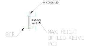
- BiColor LED Mounting Height requirement is 6.25mm +/- 0.1MM from base of LED to PCB surface
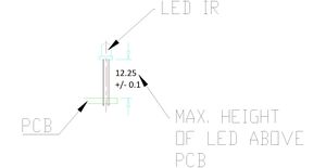
- IR Leds Mounting Height ( requirement is 12.25mm +/- 0.1MM from base of LED to PCB surface
4. Advance the board to the next Station for Top Level Assembly
Top Level Main Board Assembly
| Top Level Main Board Assembly Materials |
|---|
| Idrive X1 V7.0.x PCB |
| Lens Holders (with 2 screws each) |
| Lenses (2 per assembly) |
| Bar code Labels with Serial number |
When an Idrive X1 main board completes the SMT and hand solder process there are more assembly steps needed.
1. Bar Code Labels - Unique Serial Number Labels will be pre-generated for each Main Board in the work order. Three labels are required for each serial number(one for the main board, one for final camera case, one for the outside of the packing box). The Bar Code Label needs to be max. 22 mm x 10 mm. After SMT Assembly each Main board needs have a serial number label (supplied) affixed to the SD Card Connector. This serial number will track the main board through all processes and eventually become the camera serial number. It will be difficult and error prone for all three labels to be printed up front. I suggest that one label be printed at this stage and affixed to the Main board. Then when the main board gets put into a camera we rescan the label and print another one at that time. Same with shipping, Scan the label and print it at that station to eliminate lost of mixed up labels. What should a serial number be composed of? Manufacturer code, board version, unique number for that board?
2. Mounting of the two Lens Holders Mounting to the board.
3. Inserting the lenses in the Lens Holders.(Lenses are glued after programming and focus)
4. Advance the Top Level PCB assembly to the Programming Station
Device Programming Stage 1
| Idrive X1 V7 Programming & Lens Focus Materials |
|---|
| Idrive Top Level Main Board Assembly |
| Programming SD Card with Firmware Files |
| Super Glue (for fixing lenses) (Loctite Control, Extra Time) |
Automatic Initial Programming Idrive X1 Board
Initialize Programming Station
V7 Programming Station Initialization
Setup X1 Board
1. Insert the Programming SD card with the Firmware files into the board to be programmed.
2. Place the Idrive X1 board in to the Device holding Fixture.
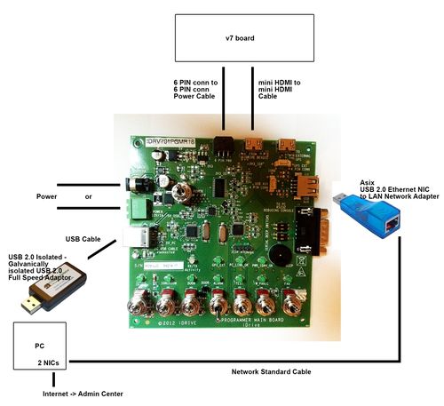
3. Connect the Power cable between the Idrive X1 Board and the Programming Fixture.
4. Connect the MINI HDMI cable between the Idrive X1 Board and the Programming Fixture.
<br\><br\>
Automatic Install
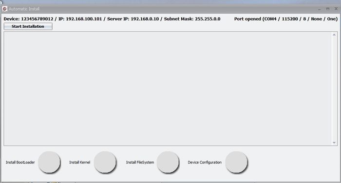
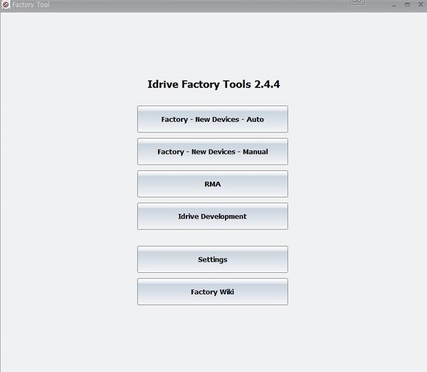
1. Click on the Factory-New Devices-Auto button to open The Automatic Install window
2. Scan the Bar Code label with the serial number (if no bar code scanner is available type the serial number from the bar code label on the SD card socket into the serial number input field in the Idrive Factory Tools Application)
3. Click on the Auto Install Button and the Automatic Install window will open
4. Click on Start Installation Button
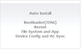
- The program will automatically step through the programming sequence and report status of each step.
- Installing Boot Loader
- Installing Kernel
- Installing FileSystem
- Configuring Device
- Contacts Admin Center to get settings for the device
- Tests Door Wire Event
- Tests Panic Wire Event
- Tests Alarm Wire Event
- If any of these steps fail the program will stop and give an error. If all steps are successful the program will enter into Lens Focus Mode.
Verify That the IR LEDS are working
1. Use a camera phone or camera and view the IR LEDs and verify that they are all on.
Lens Focusing
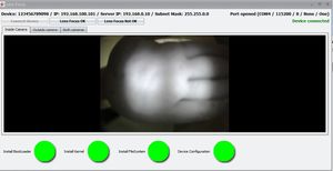
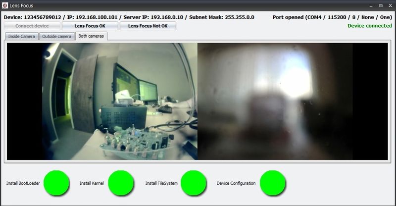
1. Select "Inside Camera" Tab an Focus the Inside camera(Driver Side) (the one on the same side of the camera as the LEDs). The focal length for the inside camera should be ~1.5 meters
2. Select "Outside camera" Tab and Focus the Outside camera (Road Side) (the one on the side of the camera without LEDs). The Focal Length for the outside camera should be as far as possible
3. Once focused fix the each lens with a drop of super glue.
4. Verify that the lenses can not move.
5. Select "Both cameras" Tab and Verify the lenses are focused.
6. If images are focused and clear click on the "Lens Focus OK" button and the focus mode will close. If the image is not clear for some reason click on the "Lens Focus Not OK" the focus mode will exit so corrective action can be taken
7. Remove Firmware SD Card and replace it with the production SD Card.
* All SD cards need to be unlocked (all SD cards have a lock/unlock switch). It depends on the SD Cards provider whether or not the card needs to be formatted. In all cases if the SD Card needs formatting do not use the quick version.
8. Advance the Main Board to the Camera Top Level Assembly Station.
Device Programming/Testing Stage 2 (Wifi, GPS, Shock Event, Transfers)
Note: The V7 programmer can be used to perform this portion of the programming provided a wireless router is configured and connected to the system. For better throughput and to reduce the number of wireless networks in a factory environment it is recommended that the x6 Programmer be used. Because this document is intended to support production the x6 programmer process is shown here. See V7 programmer final programming process section in the Appendix for use of the V7 programmer for this portion of the process.
<br\><br\>
Testing the Unit(s)
1.Initialize x6 programming station
x6 Final Test Station Initialization
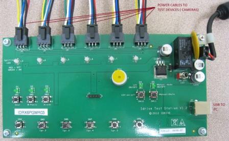
2 Plug up to 6 cameras into the x6 programmer
3. Scan the Bar Code labels with the serial number for each camera. ( camera must have a serial number lable attached to the outside of the case)
4 how does the process start and run with the x6 programmer?. how will the Factory tools run the x6 fixture automatically? If so what are the steps. Click on Transfer and Play and it goes?
5. what happens?
6. Pause the program to shake the camera and test the accelerometer(s) How can we do this?
7. When both LED return to green turn the Ignition OFF.
8. The camera device will automatically WIFI download the event to the computer station. The device will automatically show up in the connections list.
p. Press "Play events" link for each device and play the events.
1. Press Finish button on the Factory Tools
2. Disconnect the power cable and the adapter
<br\><br\>
Review Events
1. Check for focus and image quality
2. Verify that one of each type of event is present
3. Verify that the audio is working
4. Verify there is GPS data
Appendix
Idrive V7x Programming Station Documentation
| Programming Station Components |
|---|
| Computer with Monitor and speaker(s)(see requirements below) |
| Idrive V7 Programmer |
| Internet Connection |
| USB NIC (Requires Asix AX88772A Chip set) |
| USB Isolator |
| USB Cable type B to type A max. 1.5m |
| HDMI Cable (Type C male to Type C Male) 1 meter max |
| Idrive Power Cable 6 PIN to 6 PIN |
| 2 Cat 5E Cables (internet connection, Programmer connection) |
| Stabilized Power Supply 12V, 1A Minimum |
| Bar Code Scanner |
| Lens Focus Charts |
| Camera Phone |
| SD Card (with firmware and filesystem files) |
| SD card reader – primarily for RMA activity to recover events from the SD card |
<br\><br\>
Computer Hardware Minimum Requirements and Setup
| Computer Hardware Minimum Requirements |
|---|
| Monitor (needs to support 1600X1200 screen resolution) |
| Speaker(s) |
| Windows XP or better, Windows 7 Professional recommended |
| 1GB RAM |
| 100 GB Hard Disk |
| 2 Network adaptors (NICs) |
Network Adapters LAN settings:
- Connection one for the Programming Fixture
- - IP address: 192.168.0.10
- - Subnet Mask: 255.255.0.0
- - Default gateway: Blank
- - Connection two for local network with access to internet
- - DHCP or as required by location
<br\><br\>
Computer Software Requirements
- TeamViewer V5 (http://www.teamviewer.com ) - personal license. Install TeamViewer - during setup you need to choose the Personal license installation!
- A HyperTerminal application – Putty (http://www.putty.org )
- OpenJTAG Driver for USB
- Bar Code Scanner Software - need to create
- SDFormat tool the ( http://www.sdcard.org/consumers/formatter_3/eula ) DO NOT USE THE QUICK FORMAT Use the “Full(rewrite) option!
- Idrive Factory Tools 2.2.0
V7 Programmer Connections
<br\><br\>
V7 Programmer Switches
File:V7-Programmer-switches.jpg
<br\><br\>
V7 Programming Station Initialization
<br\><br\>
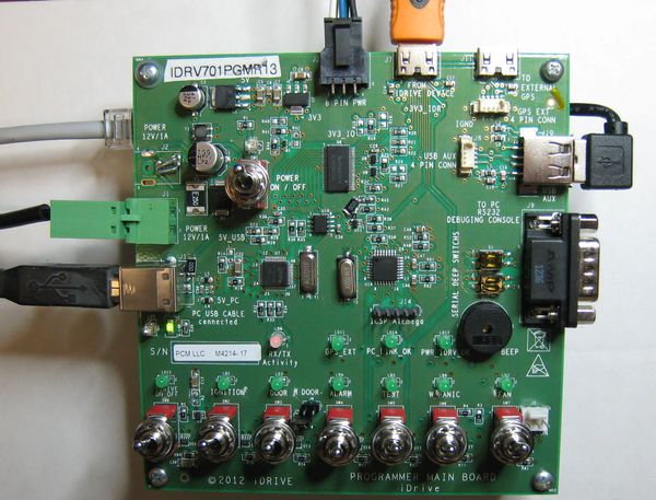
1.Configure Switches on the V7 Programmer
Ensure all switches are in the off position as shown.
Turn On the Power switch and leave the programmer on for the batch of boards.(you do not need to turn it off to program the next board)
Note: In auto programming mode only the Power Switch is used. The other the switch functions are controlled via software
2. Launch the Idrive Factory Tools 2.0 Application
- Factory-New Devices-Auto
- Select for Automatic programming of New Idrive X1 Devices (Most commonly used mode)
- Factory-New Devices- Manual
- Select for Manual Custom Programming of New Idrive X1 Devices
- RMA
- Select for RMA processing of Existing Idrive X1 Devices
- Idrive Development
- For internal Idrive Development use only
- SETTINGS
- Select to set Port number or non-standard IP addresses
- Factory Wiki
- Factory Manual on Admin Center
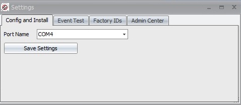
3. Configure Application Settings for the Programmer
Click on Settings
Set the port number for the fixture.
(Port number can be checked in "Control Panel> System and Settings> Administrative Tools> Computer Management> Device Manager> Ports)
- Set Port number or non-standard IP addresses
4. Select Programming Mode (Normally Auto)
- Click on Factory-New Devices-Auto
- Serial Number field
- 12 character serial number for the device to be programmed as read from the bar-code label on the Motherboard. The serial number can be typed in but usually it is filled in by the bar code scanner. After the field is populated press enter and the Auto Install Button will become active. We need error checking for correct serial number length and to ensure the previous serial number is not being used. If they forget to scan the new board the serial number from the old one will be used again.
Proposed S/N format- 2 digits for vendor| 3 digits for Board Version| 7 digit Serial number field Example 01|704|0000001
- Auto Install Button
- A valid serial number must be entered for the button to be active. When selected it will open the The Automatic Install window (see below)
- Lens Focus
- Reenter Focus mode for a device that previously failed this step.
- X1 / X1-P / X1-3G
- Selects X1 Camera Features. Supports the 3G version of the camera and this is set in the Final Programming process.
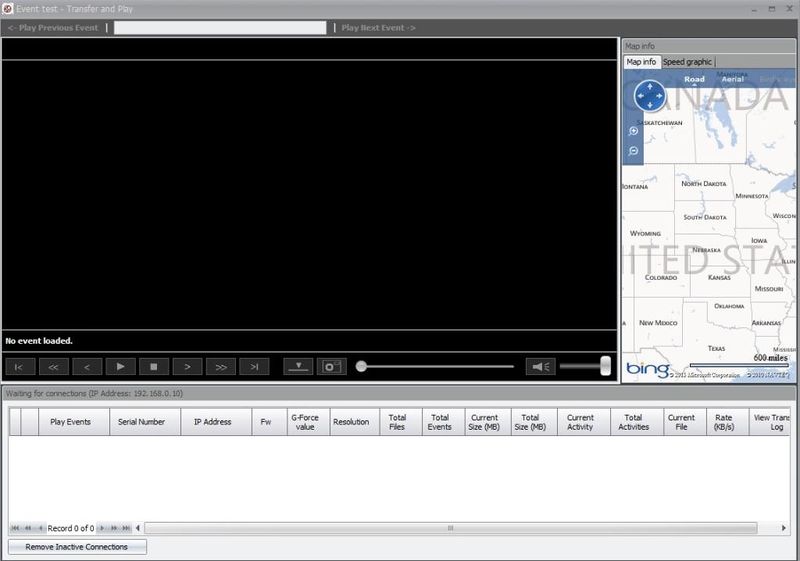
- Event Test-Transfer and Play
- For Review of Events transferred from programmed X1 series board in the Final Programming Station
- Settings
- Set the Port number to look for the programming fixture
- Factory Wiki
- This document on the Idrive Admin Center
V7 DUT Holder
File:V7-DUT-holder.jpg DUT holder Frame
<br\><br\>
"V7 programmer final programming process"
words here
<br\><br\>
Idrive x6 Programming Station Documentation
<br\><br\>
Idrive x6 Final Programming Station Requirements
| Final Programming Station Components |
|---|
| Computer with Monitor and speaker(s)(see requirements below) |
| Idrive x6 Final Programmer |
| Internet Connection |
| USB Cable type B to type A max. 1.5m |
| Idrive Power Cables 6 PIN to 6 PIN |
| 2 Cat 5E Cable (internet connection, Wireless router) |
| Stabilized Power Supply 12V, 6A Minimum |
| Bar Code Scanner |
| Wireless router |
| SD card reader – primarily for RMA activity to recover events from the SD card |
<br\><br\>
Computer Hardware Minimum Requirements and Setup
| Computer Hardware Minimum Requirements and Setup |
|---|
| Monitor (needs to support 1600X1200 screen resolution) |
| Speaker(s) |
| Windows XP or better, Windows 7 Professional recommended |
| 1GB RAM |
| 100 GB Hard Disk |
| 2 Network adaptors (NICs) |
Network Adapters LAN settings:
- Connection one for the Programming Fixture
- - IP address: 192.168.0.10
- - Subnet Mask: 255.255.0.0
- - Default gateway: Blank
- - Connection two for local network with access to internet
- - DHCP or as required by location
<br\><br\>
Computer Software Requirements
- TeamViewer (http://www.teamviewer.com ) - personal license. Install TeamViewer - during setup you need to choose the Personal license installation!
- A HyperTerminal application – Putty (http://www.putty.org )
- OpenJTAG Driver for USB
- Bar Code Scanner Software - need to identify
- SDFormat tool the ( http://www.sdcard.org/consumers/formatter_3/eula ) DO NOT USE THE QUICK FORMAT Use the “Full(rewrite) option!
- Idrive Factory Tools 2.2.0
x6 Final Programmer Connections
<br\><br\>
x6 Final Test Station Initialization
1.Configure Switches on the x1 Programmer
Ensure the power switch is in the off position as shown.
2. Launch the Idrive Factory Tools 2.0 Application
This opens the transfer and Play window
Wireless router Setup
- LAN IP address 192.168.0.1
- Network Mask 255.255.0.0
- Default Gateway Blank
- SSID bwifi
- No DHCP
- No DNS
- No encryption
- No WAN settings (not in use)
<br\>


