3G DVR User Manual
Product Introduction
Product Summary
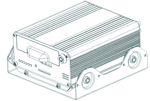
The DVR (Automotive) is a cost-effective, functional and scalable device designed for video surveillance of your mobile assets. It uses a high-speed processor, an embedded Linux platform and combines the most advanced IT processes(H.264 Video Compression/Decompression, 3G and GPS positioning technology) and the best Product structure design(Double shockproof ). DVR enables CIF, HD1 and D1 video formats to record. The DVR can be record drivers' many driving information, such as driving route/speed/video/audio and others, recording data are uploaded to HDD or SD Memory Cards. A DVR centric software platform (CMS) can be realized with links to a Central Alarm monitoring system for remote management and playback analysis, It's make company or personal very easy to manage the vehicles. The DVR may look simple in its exterior design, provides powerful auto black box features, installation flexibility and high reliability.
Main Parameters
| Items | Parameters | Specifications |
| System | Language
OSD Password |
Chinese/English
Graphical User interface(OSD menu) Users Password/ Administrator Password |
| Vision | Video input
Video output Preview Recording Ratio Image Compression |
4-CH video input 1.0Vp-p,75Ω
1-CH video output 1.0Vp-p,75Ω Support 1 channel or synchronous 4 channels preview. PAL -25 Frame/s NTSC -30 Frame/s H.264 Main profile |
| Audio | Audio input
Audio output Recording mode |
4-ch Audio input 600Ω
1-ch Audio output 600Ω Audio & Video sync. |
| Image processing & storage | Video format
Video stream
Audio Bitrate Storage |
4-ch CIF: 25fps, 4-ch HD1: 25fps, 1D1: 25fps + 3CIF: 25fps
ISO14496-10 CIF: 1536Kbps ~ 128Kbps,6 levels optional. Highest:1 level HD1: 2048Kbps ~ 380Kbps,6 levels optional. Highest:1 level D1: 2048Kbps ~ 400Kbps,6 levels optional. Highest:1 level 4Kbytes/s SATA 2.5’’ hard drive (support to 2T)and SD card storage(support to 64GB) |
| Alarm | Alarm input | 4 switching value |
| Wireless Transmission | 3G(EVDO/ WCDMA) | Built-in 3G(EVDO / WCDMA) module |
| GPS | Built-in GPS module, Geographic co-ordinates, speed can be read in coding flow,and can be wireless uploaded. | |
| Software | Analysis of PC playback
CMS |
Video playback on PC,and analysis the vehicle info in the file.
Video preview via GPS upload、alarm upload, central command and parameters configuration, etc. |
| Upgrade | Support SD cards upgrade. | |
Main Functions of the Product
| Function | Functions description |
| Recording | 1. Support four video mode: Manual recording, time recording, motion detection recording, Alarm recording
2. Support 1 channel D1 or synchronous 4 channels CIF recording. 3. Support PAL System and NTSC System. 4. OSD overlay recording, such as time, Bus No., Channel’s name, Stops information etc 5. Support HDD and SD Card storage recording. 6. Support HDD and SD Card circulating record. |
| Preview | Support 1 channel D1 or synchronous 4 channels CIF preview. |
| Playback | 1. Support 1 channel playback
2. Support 4 channels playback 3. support play, pause, frame into, slow play, fast forward, upper section, next section and mute function 4. Video/File retrieval: Support time retrieval, channels retrieval and video type retrieval. |
| Alarm | Support local signal alarm, motion detection alarm and abnormal alarm. |
| Information record | Support Vehicle No, driving route, device No record. |
| ON/OFF Control | 1. Support fixed timing starting up and shutdown
2. Support Car Key (ACC) switch or ACC delay switch. |
| Upgrade | Support automatic upgrade and manual upgrade |
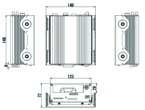
Diagram Specification
MDVR Installation
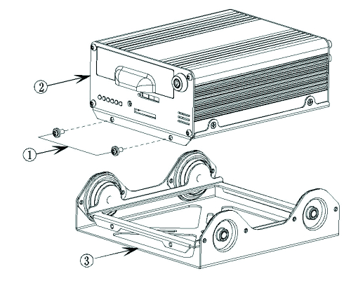
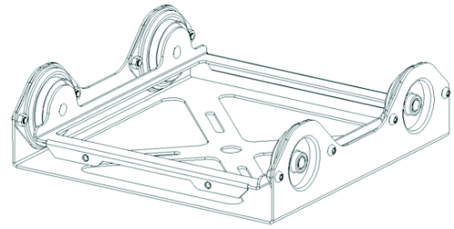
Set the main unit and shockproof mount apart
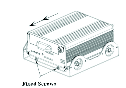
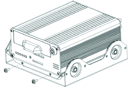
Unfasten the two main screws of the DVR with a screw driver and remove the shockproof mount.
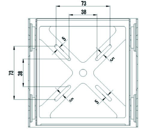
Install the shockproof mount
Please installed the shockproof mount on an appropriate place (under the front Passenger’s seat or other side / wherever convenient)
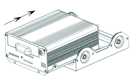
Install the DVR into the shockproof mount again, and fixed screws
Hard disk installation
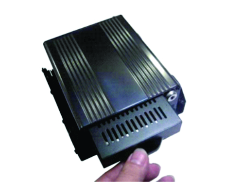
Remove the HDD case from the DVR
Turn the key to off state, and remove the HDD case.
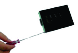
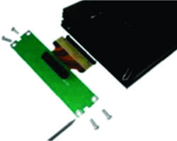
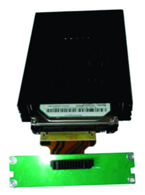
Take the SATA connector out from the HDD Case
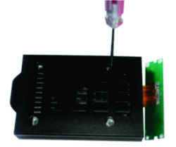
Remove the 4 screws on the backside of he hard drive case, then take the SATA connector out from the hard drive case.
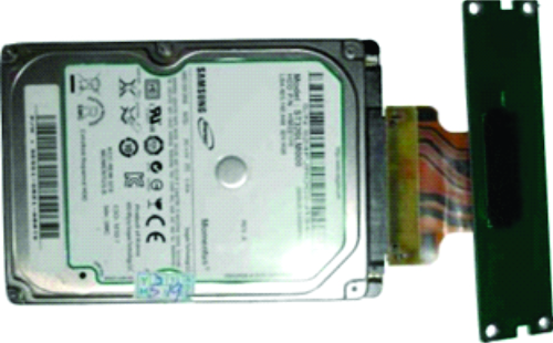
Connect the SATA board with the SATA hard disk
Put the SATA hard disk into the shockproof case
Note: The hard disk must be float inside the bracket of HDD Case.
Fasten the hard disk tghtly bt another 4 screws
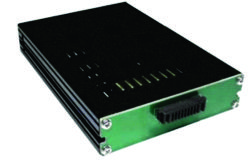
Install the connector back to the back side of hard drive case; turn 180 degrees of the HDD case and fixed the back screws. Then the SATA hard drive is installed into the hard drive case.
Cables function and accessories instruction
Power supply cables
| Pin | Color | Description |
| 1 | RED | Positive (connect it to the “+” of power supply) |
| 2 | YELLOW | Ignition signal. Connect this wire to “+” of power supply if you don’t use ignition to control the power. |
| 3 | BLACK | Negative (connect it to the “-“ of power supply) |
Video/Audio input cables
| Mark | Description |
| VIN (PIN1) | Video input (yellow) |
| AIN (PIN2) | Audio input (white) |
| 12V (PIN3) | Power output “ +”(12V,Max 1A),Can connect with Camera |
| VIN (PIN4) | Video input (yellow) |
| AIN (PIN5) | Audio input (white) |
| GND (PIN6) | Ground and signal “-“ |
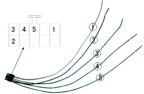
Signal cables / IO Alarm cables
| Mark | Color | Description |
| ①RS485_B- | Whit green with black side | Control PTZ |
| ②RS485_A+ | Blue green with black side | Control PTZ |
| ③Sensor 1 | Green with black side | Sensor (alarm), such as backing screen switch |
| ④Sensor 2 | Green with black side | Sensor (alarm), such turning right the screen switch |
| ⑤Sensor 3 | Green with black side | Sensor (alarm), such as door open screen switch |
Video/Audio ouput cables
| Mark | Description |
| VIN (PIN1) | Video input (yellow) |
| AIN (PIN2) | Audio input (white) |
| 12V (PIN3) | Power output " +" (12V,Max 1A), Can connect with Camera |
HDD Reader
Use for data transferred: From HDD to PC
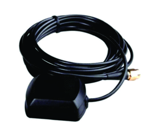
GPS antena
GPS information pick up, such as speed, coordinate, Google map etc.
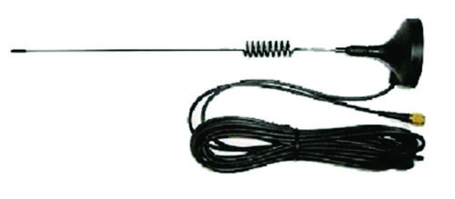
3G antena
Structure introduction of the Product Appearance
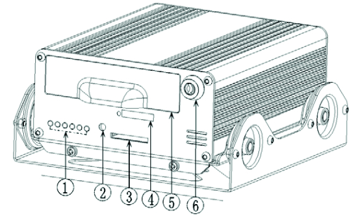
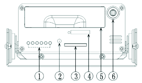
Front Panel
①:LED light: 1.PWR, 2.RUN, 3.ALM, 4.REC 5.VLS. 6.SD
1. PWR(Power): the power led will turn red when the power is connected; after soft-shutdown the device, the power led will become green.
2. RUN: this led will flash when the device is working properly; after soft-shutdown the device, it will turn off.
3. ALM(Alarm): when there is any channel alarm input, this led will turn on.
4. REC(Record): when the HDD is recording, this led will turn on.
5. VLS(Video loss): where there is any channel video loss, this led will turn on.
6. SD: when the SD card is detected, the SD card led will turn on.
②:IR, Remote control receiver
③:SD slot
④:SIM Card Slot
⑤:HDD shock box
⑥:Lock: To lock and protect the HDD; For ignition and soft close.
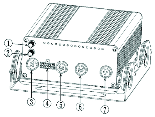
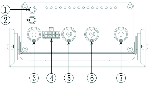
Rear Panel
①:GPS antenna port
②:3G antenna port
③:AV output
④:IO input
⑤:CAM1, CAM2, AV input
⑥:CAM3, CAM4, AV input
⑦:POWER IN DC 8V-32V; Ignition IN.
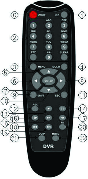
Remove Control
| 0 POWER
1 DEV 2 Enter numbers and letters
3 MENU 4 MULTI 5 UP 6 LEFT 7 ENTER 8 RIGHT 9 SHIFT 10 DOWN 11 ESC 12 REC 13 PLAY 14 PAUSE 15 SLOW PLAY 16 FAST FORWARD 17 FAST REVERSE 18 PREVILUS 19 NEXT 20 FN 21 VOIP 22 MUTE |
Instruction of some buttons:
POWER: turn on/off the recorder
FN:
- used to select specified file in the recording file list, in order to backup file.
- used to switch the input method of the soft keyboard.
- change the selected status in the motion detection area setting and blind area setting.
MENU:
- call out main menu
- used to exit the soft keyboard
- used to clear all the area setting
MULTI: used to set 4-picture or 1-picture view
SHIFT: used to display/hide control bar when playback.
ESC: cancel and exit the current menu.
PLAY: used to enter the file and search page in order to play recording file.
VOIP: the shortcut of the backspace key in the soft keyboard; select all when set motion detection setting area.
MUTE: sound/mute setting when playback.
ENTER: save and exit the current menu.
