Difference between revisions of "Stonkam D8 Initial Configuration and Setup"
| Line 59: | Line 59: | ||
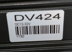
There is a sticker on the bottom of the unit with '''DV424''' in large font and a bar code. Record the serial number as '''424''' followed by the number under the bar code. I.e. 4241730 would be conventional in the below example. | There is a sticker on the bottom of the unit with '''DV424''' in large font and a bar code. Record the serial number as '''424''' followed by the number under the bar code. I.e. 4241730 would be conventional in the below example. | ||
| − | [[File:D8_Serial.jpg | + | [[File:D8_Serial.jpg|none|250px|]] |
<br> | <br> | ||
Revision as of 22:19, 15 August 2017
Necessities
What you will need:
- New D8 unit w/ accessory kit
- New SSD
- Power Supply
- Power & Ground banana plugs to 8 pin power cable
- A input/output medium, i.e.
- Remote control + 6 pin to RCA cable with RCA to USB adapter for viewing on Amcap software (yellow is video)
- Remote control + D8 monitor
- D8 Touch Screen monitor
NOTE: the 6 pin video out is labeled "Panel" on the D8
The D8 will turn on with the power supply, there is no intermediate power switch (contrary to the D4 DVRs).
Login
Admin Account
User Names are case sensitive
Default user name admin
Default password 123
After Config:
user name admin
password IdrD8
Not yet implemented
Change admin to: IDRIVE Need to verify when we receive another D8. I do not want to lock us out of the only one we have.
Password: IdrD8 Is this OK?
Guest Account
The Guest account limits Menu Access to Playback and Volume only
Default "Guest User name : guest
Default Guest Password: 321
Change Guest to: bnsf
Password: 249805 (SB street address and area code)
Routine Setup
Document Serial Number
There is a sticker on the bottom of the unit with DV424 in large font and a bar code. Record the serial number as 424 followed by the number under the bar code. I.e. 4241730 would be conventional in the below example.
Install Batteries in Remote Control
From the accessory kit.
Install and Format Hard Drive
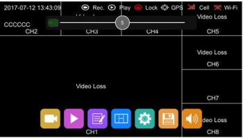
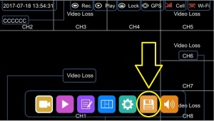
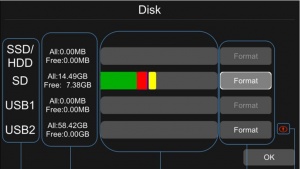
Click on the Floppy Disk Icon on main display
Wait for a format successful message. (this should take approximately 5 minutes for a 500GB hard drive)
Upgrade Firmware and Verify
Get current version from AC
Install Config File for vehicle type (Handler or Crane)
Stonkam BNSF Crane Config File
Stonkam BNSF Loader Config File
Install SIM Card Installation
Set device/vehicle specific settings (tag device with vehicle number) (document on traveler)
- License No. (vehicle name)
- Device No. (DVR Serial number) (EX: 4241730)
- Time Zone – verify time correct for that zone
- Anything else specific to this one device?
Save Configuration to hard drive
If saved to the hard disk the disk might get moved to a different vehicle.
Add an SD card to the system for this purpose? - SD Cards will not format at this time
Rename the config file so it does not get deleted if imported
Labels
- Idrive Sticker In/On security Box (Advertising)
- Label on top of DVR showing (So Installer and Customer can identify the device for support)
- Vehicle Name
- DVR S/N – (424)and the 4 digits on the unit example: 4241730
- SIM S/N
- Download (template requires Zebra Designer software to open)
Remove Film from Door Window
There is a protective film on the front door to protect the plastic
Mount DVR into the Security case for shipping
- Mount in Security case for shipment
Pack DVR For shipping
- Place 44Pin Cam Cable, Power cable, GPS/3G Antenna, Remote, DVR Keys, Security Box Keys in a box
- Label the outside of the box with the vehicle name
Enter DVR into Admin Center
- Set Warranty Date
- Document SIM Number
Assign (name) SIM In Podsystems (Activate when and by who?)
Kit the other items for the vehicle (Cameras, Cables)
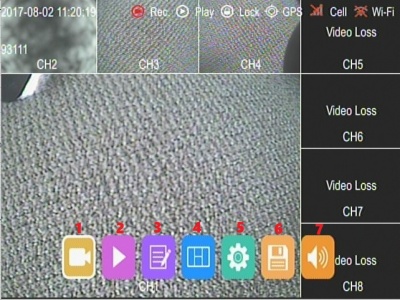
Main Menu
The Main Menu is Displayed by pressing Menu on the remote. If using a touch screen touch the bottom half of the screen. Entering any of these menus will stop the device from recording.
- 1)**Manually Control - Record, Play, Stop, FF, RW
- 2)**Playback - Search by date & Time
- 3)**Logs - System & Export Logs
- 4)*Display Mode - Switch Grid view from Channels 1-4, 5-8 or 1-8
- 5)**Configuration Settings - Record,Display, Network & System settings
- 6)**Storage - Manage SSD, SD, USB
- 7)**Volume - Playback Volume
Manually Control
Playback
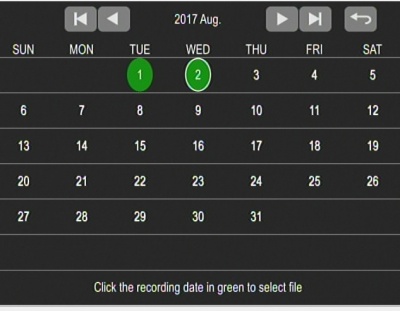
A date marked in green indicates that there were videos recorded that day.
Click the day to view the list of enter the video files for that date
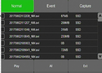
Choose the desired video and press the Play button.
- You can play single or multiple videos
- Multiple videos can be played in sequence and can shift into the next or the previous one.
Select and Play Videos
- Normal
- Event
- Capture
- Play
- All
- Exit
AL, I think "Capture" can be used to save the video to USB Stick. Might become more practical than swapping the hard drives. I have not tested this.
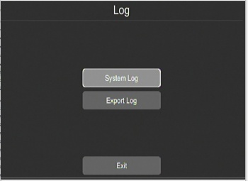
Logs
Used to keep a log of events in the system
Navigate to Menu->Setup->Log
System Log
Feature allows you to search the Systems Log of events on the machine
Video Loss not shown in Syslog? Also no "Fault" light
Export Log
Use this feature to export the system log.
Log can be exported to SSD, SD, USB
Configuration Settings
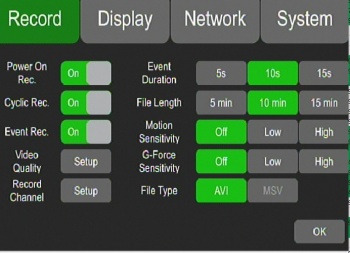
Record
- Power On Rec ON
- Cyclic Rec. - Overwrite? ON
- Event Rec. OFF
- *Video Quality - Settings for Main Stream, Sub Stream, JPG
- *Record Channel - turn on/off recording for each channel
- Event Duration - 15 Seconds
- File Length - 15 Minutes
- Motion Sensitivity - OFF
- G-Force Sensitivity - OFF
- File Type - AVI
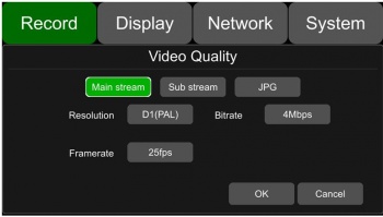
Video Quality
Main Stream
Resolution: D1(NTSC)
Bit Rate: 2Mbps
Frame Rate: 20fps
Sub Stream
Resolution: CIF(NTSC)
Bit Rate: 64Kbps
Frame Rate: 20fps
JPG
Frame Rate: LOW
Record Channel
Green means channel is enabled to record.
Loaders use channels 1,2,3,4
Cranes use channels 1,2,3,4,5,6,7,8
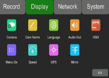
Display
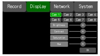
*Camera - Brightness, Contrast Etc for each Camera
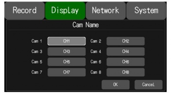
*Cam Name - Name of Channel on Display
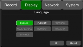
*Language - Set system Language
*Audio Out - Select Channel Audio to listen to
*Camera - Brightness, Contrast Etc for each Camera
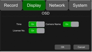
*OSD - On Screen Display Information
*Menu On - How lon Menu is Displayed before logout
*Speed - Speed Settings
*GPS - GPS Location Information
*Mirror - Mirror the Camera Image
Camera
Individual Camera settings:
- Brightness
- Contrast
- Saturation
- Hue
Cam Name
Each camera has its own channel with its own "channel name".
Navigate to the display tab by hitting Menu->Setup->Display
Choose which camera name you would like to change by selecting its associated channel name. (8 letters max)
Loader Cam Names
- CH1 - suggest: CAB
- CH2 - suggest: R-Front
- CH3 - suggest: L-Front
- CH4 - suggest: Rear
Crane Cam Names
- CH1 - suggest: CAB
- CH2 - suggest: L-Front
- CH3 - suggest: R-Front
- CH4 - suggest: Far-Side
- CH5 - CH8 - suggest: ?????? Need names for these
Language
To edit the language of the device access Menu->Setup->Display->Language
Select which language you want from the buttons presented. Languages available are English, French, German, Russian, Japanese, Italian, Austrian
Audio Out
This setting edits the output for the audio channel in split mode
Navigate to this setting by selecting Menu->Setup->Display->Audio Out
Select which camera's audio you would like to output.
OSD
OSD controls what information gets overlayed on the video of each camera.
Navigate to this setting by selecting Menu->Setup->Display->OSD
- Time - ON
- License - ON
- Camera Names - ON
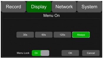
Menu On
Sets the duration of time the menu will display on the screen.
Navigate to this setting by selecting Menu->Setup->Display->Menu On
Settings: 30, 60, 120 seconds, or always on. ::*Time - 60 Seconds
The menu lock setting will lock the menu to be password protected.
A password is needed to change this setting
- Menu Lock - ON
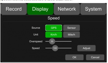
Speed
Allows you to change the source of the displayed speed to either the GPS or the vehicle speedometer as well as the units of speed to be either kph or mph
Navigate to this setting by selecting Menu->Setup->Display->Speed
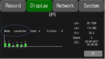
GPS
Displays information of latitude/longitude, detectable satellites, connected satellites, speed, and time
Navigate to this setting by selecting Menu->Setup->Display->GPS
Mirror
Mirrors the video output on the selected camera. Configurable to each camera
Navigate to this setting by selecting Menu->Setup->Display->Mirror
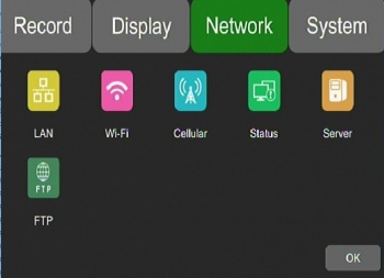
Network
*Lan - Lan Settings
*Wifi - Wifi Settings
*Cellular - Cellular Settings
*Status - Networks Status
*Server - Server Settings
*FTP - FTP Settings
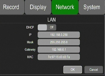
LAN
Defaults:
- IP Address 192.168.100.188 set to 192.168.0.250
- Mask 255.255.255.0
- Gateway 192.168.100.1 set to 192.168.0.1
- MAC Add: 7e:97:15:xx:xx:xx
Notes:
I can ping it but not login. There does not appear to be any access from the network only connectivity with a local server
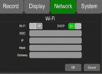
WiFi
N/A - Optional
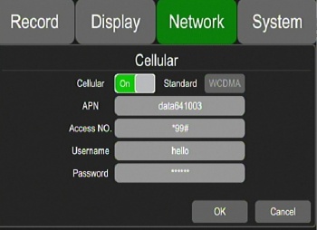
Cellular
Help, this is not working!!!
Default Port is 9090, What do we need for LTI?
I set the port 6608 to test with newdvr.idriv...
- Cellular - ON
- Standard - WCDMA
- APN - data641003
- Access No. - *99#
- User Name - BLANK
- Password - Blank
Status
Displays information on:
- Lan IP address
- MAC Address
- 3G/4G Network Status
- 3G/4G Signal Strength
- Wifi Network Status
- Wifi IP Address
- Wifi Signal Strength
- Server Status
- Network Connectivity
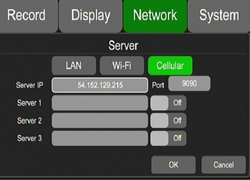
Server
I need the server settings for LTI!!!
Note: Server IP will not take a name, it needs an IP address
From Stonkam 8/11/17: "Good idea, we will add DNS function soon"
Server IP: HELP!
Port: HELP!
FTP
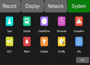
System
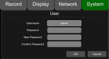
*User - User Password
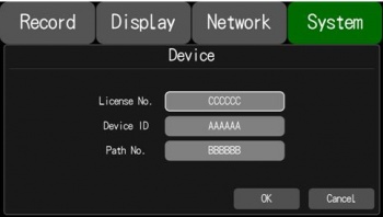
*Device - Vehicle, Device, Path information
*Schedule - Timed Recording
*Exception - Buzzer On/Off and duration
*Acc -
*Alarm -
*Update -
*Config -
*Info -
User
Device
Which gets set for alerts? License or Vehicle?
License No. - Default:(AAAAAA) Set to Vehicle Name
Device ID - Default:(BBBBBB) Set to Device Serial number? Example 4241730
Path No. - Default (CCCCCC) What is this?
From Stonkam 8/11/17 "it is a feature reserved for adding bus number in the future if the customer needs"
Date & Time
Set for customer location
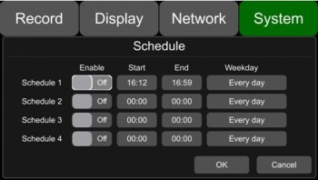
Schedule
Used to schedule up to 4 recording tasks.
Recording settings include a start & end time as well as day of the week to record.
Note: Recordings are permitted to overlap
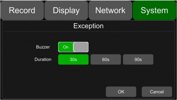
Exception
Settings to configure a buzzer when certain errors occur.
Example: Buzzer when camera becomes disconnected
ACC
Displays:
- Current voltage of the DVR
- Shutdown voltage- If voltage < shutdown voltage then dvr shuts down, powers back on only when voltage exceeds shutdown voltage
- ACC Delay- Continued recording after ACC is disconnected. Options are 5,30,60 seconds
Note for ACC Delay the manual states that options are 5,10,15 seconds so there is conflict on which is true
Alarm
Update
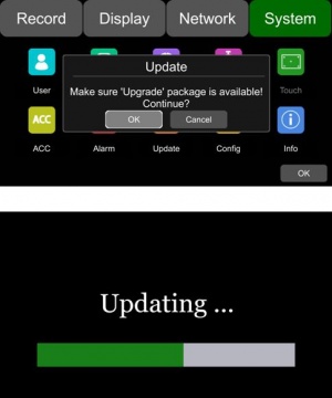
Update of Firmware removes all configuration settings!!!
From Stonkam 8/11/17 " Because the firmware is not totally settled for now and we will upgrade it sometimes according to your specifc needs, so it will modify the configuration file when ungrading. after the firmware is sort of settled, it can keep the customer's setting while upgrading. May also cause the D8 to beep uncontrollably until the config is loaded."
Process takes ~ 3 Minutes
Ensure you are using the latest FW version (Stonkam Firmware 20170807)
Eric's note: USB would not mount unless first formatted in the D8. Windows will see the D8 formatting as something it needs to "scan and fix". Do not "fix" this.
Copy the firmware to USB stick or SD card root directory.
Insert the USB Stick into the DVR.
Either:
- Reboot the DVR or
- Navigate to Menu -> Setup -> System -> Update> Hit OK
Wait for Update Success!
Verify that the update was successful by Menu -> Setup -> System -> Info
Compare the current version to the desired version.
Upgrade Notes
Currently, the upgrade package is deleted from the USB stick after the upgrade process is finished. To prevent having to recopy the firmware to the USB stick rename the file.
Example of Firmware Name: “dv424_upgrade_2017xxxxxxxx”
Change Name to : “dv424_upgrade_never_rename”
Step 2:Copy the package to USB disk or SD card root directory, and insert it to DVR.
Step 3:Power off the DVR and reboot it, then it will auto upgrade. Or in the menu Menu -> System -> Update, click OK to confirm to upgrade. Both method can start the upgrade process.
Eric's note: rebooting the DVR with a "never_rename" firmware file inserted will cause the system to loop
Config
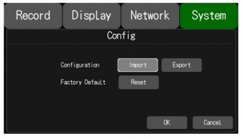
Import
Insert the USB with the appropriate configuration file sv_xml.xml in its root directory
Eric's note: filename must match exactly, you might have to rename if downloaded from the AC
Select the import button
Export
Select Export, Select location (SSD or USB or SD)
Saves sv_xml.xml to location
Info
Displays system software version number
Update the picture with the current (new) version
Installed version was:
- SYS Version:201705221746
- MCU Version: Not shown
- UID : 1705080007
Latest Version we received on 8/7/17 is:
- SYS Version: 201708070904
- MCU Version: 2017080215
- UID : 1707270002
Storage
Filesystem Structure
Log4Gui - ASCII System Log
test_writable - system test if disk read only?
Normal Folder - location where videos are stored
- 20170801 Folder - separate folder for each date
- Video files naming example: 20170801150248_NM_0030_0001_1920_1080_25_04194304_AAAAAA_02.avi
- 2017^08^01^ - Year^Month^Day
- 15^02^48 - Hour^Minute^Second (from start?)
- _NM_0030_0001_1920_1080_25_04194304_ Figure this out
- AAAAAA_02 - Vehicle_Channel
Volume
Set the playback volume via the remote. The default volume is 5.
Minimum volume: 1
Maximum volume: 10
Detailed Assembly Instructions
Hard Drive
Hard Disk Installation Detail
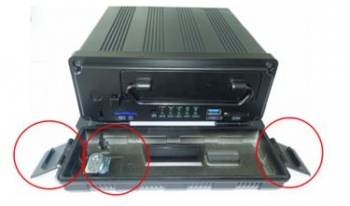
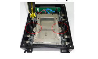
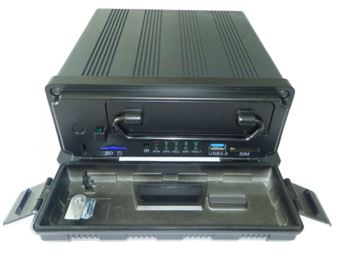
Step 1: Unlock the device with its key, and open the two side flaps on the front panel. Pull the front plate from the top down as shown.
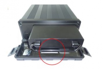
Step 2: Pull the hard drive sled out by its attached ring
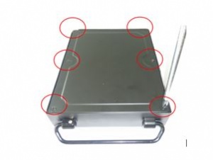
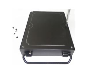
Step 3: Remove the six screws that hold the hard drive sled together carefully with a screwdriver. Once these screws are off the whole bottom plate should be removed.
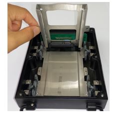
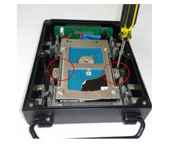
Step 4: Remove the two screws on the silver hard drive support shelf. Once these are removed pull the top of the shelf up as illustrated.
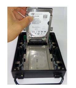
Step 5: Slide the new hard drive into the enclosure making sure a solid connection is made with the hard drive.
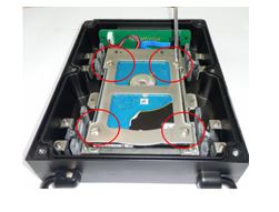
Step 6: Fold the hard drive shelf back down into its resting position and secure the 4 hard drive mounting screws in place. These hard drive mounting screws come from the device's accessory pack
Step 7: Lock the hard drive shelf into place with the 2 securing screws from step 4
Step 8: Reinstall 4 Hard drive Sled screws that secure its bottom panel.
Step 9: Slide hard drive sled back into the D8 securely
Format Hard Disk Detail
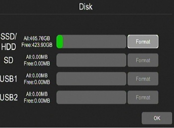
Format SSD (15 seconds for 500GB)
Press the orange floppy disk icon to access the disk management settings
Select which disk you would like to format.
Note once formatted all data on this disk will be lost
Acknowledge that you would like to proceed with the format.
Wait for a format successful message. (this should take approximately 5 minutes for a 500GB hard drive)
SIM Card Installation
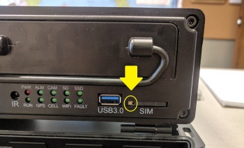
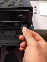
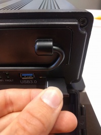
Push the Eject button (shown in yellow) to the left of the SIM Slot with a pen and remove SIM Tray
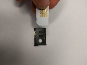
Document SIM Number and Insert SIM Into Tray Such that it sits flush with the plastic tray
- Note: Sim is held in under tension by plastic wedges inside the tray
Insert Tray into System, ensure it clicks in.
Firmware Versions Changes/Notes
Aug 8th 2017
Server address will not take a name only an IP address
SD cards will not format
Configuration is lost when firmware updated
Video Loss does not create a syslog entry or turn on the fault LED
Next Version
