Difference between revisions of "Video Splitter Assembly"
| Line 8: | Line 8: | ||
[[File:D8_PCB_Install_1.jpg|400px|]][[File:D8_PCB_Install_2.jpg|400px|]] | [[File:D8_PCB_Install_1.jpg|400px|]][[File:D8_PCB_Install_2.jpg|400px|]] | ||
| + | |||
| + | <br><br> | ||
===Step 2: Affix the Input Face-plate === | ===Step 2: Affix the Input Face-plate === | ||
Revision as of 21:10, 10 August 2017
Process for Assembling an idrive 4 channel video splitter
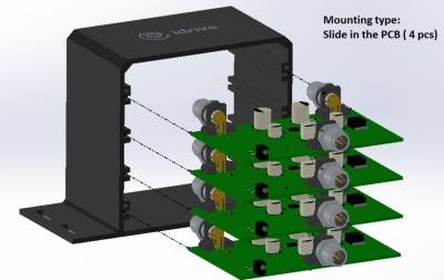
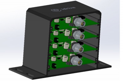
Step 1: Mount the 4 PCB Boards
- Slide Each PCB board sequentially in the 4 slots, making sure all boards have the same orientation as in the images below
Note: Use the idrive logo on the case as a reference point when determining correct orientation
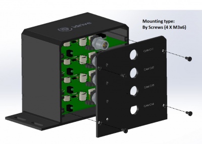
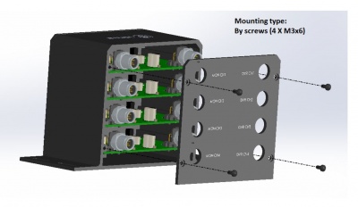
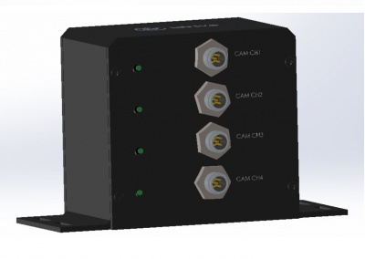
Step 2: Affix the Input Face-plate
Note: The input side of the PCB has only 1 plug as well as four small led indicator lights
- Place the Input face-plate flush with the input plugs and use four of the provided screws to secure it to the case
- Apply BLUE Locktite to screw threads.
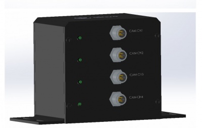
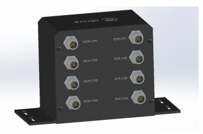
Step 3: Affix the Output Face-Plate
- Place the Output face-plate flush with the output plugs and use four of the provided screws to secure it to the case
Note: The output side of the PCB has 2 plugs
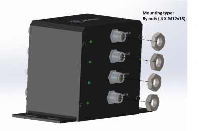
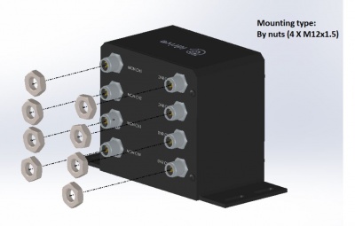
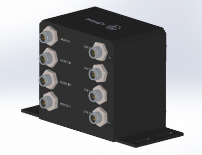
Step 4: Secure 4 Input Nuts
- Fasten the 4 input nuts tightly to the case as in the image below
Step 5: Secure 8 Output Nuts
- Fasten the 8 output nuts tightly to the case as in the image below
Schematics and Details
Assembly Procedure PDF
File:Video Splitter Assembly Procedure.pdf
3D PCB Rendering
File:Video Splitter 3D PCB Rendering.pdf
PCB Scematic
File:Video Splitter Scematic.pdf
Adapter Cable Technical Drawings
5P Female to MiniDin 4p Male FOR Cable: File:Video Splitter 5pFemale to 4pMiniDinMale.pdf
5P Female to MiniDin 4p Female FOR Cable: File:Video Splitter 5pFemale to 4pMiniDinFemale.pdf
4P Female to GX 4P Female FOR Cable: File:Video Splitter 4pFemale to 4pGXFemale.pdf
Cable Notes
1. RTH-605-1043 = 4pin MiniDin-Male (S-video connector) to M12 5pin -Female = cable that connects video splitter to ECCO Video Monitor
- RTH-605-1043 = M2S cable (monitor to splitter)
- MiniDin-M connector of M2S cable plugs into ECCO monitor connector and M12-5pin connector goes to connector J1 of video splitter (Nor/Mirror, Audio signals and power are passed through Video spliter board)
2. RTH-605-1044 = 4pin MiniDin-Female (S-video connector) to M12 5pin -Female = cable that connects ECCO_C2000 camera to video splitter
- RTH-605-1044 = C2S cable (camera to splitter)
- MiniDin-F connector of C2S cable plugs into C2000 camera connector and M12-5pin connector goes to connector J3 of video splitter (Nor/Mirror, Audio signals and power are passed through Video spliter board)
3. RTH-605-1045 = M12 4pin - Female to GX12 4pin -Female (Aviation type) = cable that connects video splitter to Idrive DVR
- RTH-605-1045 = D2S cable (DVR to splitter)
- GX12(aviation) connector of D2S cable plugs into Idrive DVR and M12-4pin connector goes to connector J2 of video splitter (only video signal and ground are normally going to DVR, the audio will be available to DVR, only, if you place jumper on J4)
Note: The M12(picture attached) connector is NOT Aviation type , GX12 connector (the one that goes to Idrive DVR) is the only Aviation type connector used.
The Video splitter is powered by the ECCO monitor and C2000 camera is also powered from the ECCO monitor , the other signals present at C2000 connector are passed-through the Video Monitor.
Idrive DVR has only Video signal and GND (obviously we need that) in common with Video splitter, audio signal is optional (by placing J4 jumper).
