Difference between revisions of "Video Splitter Assembly"
Jump to navigation
Jump to search
| Line 1: | Line 1: | ||
| − | =Process for Assembling an idrive 4 channel video splitter | + | =Process for Assembling an idrive 4 channel video splitter= |
=== Step 1: Mount the 4 PCB Boards === | === Step 1: Mount the 4 PCB Boards === | ||
| Line 36: | Line 36: | ||
[[File:D8_Splitter_Out_Nuts.jpg|400px|]] [[File:D8_Splitter_Out_Nuts_2.jpg|400px|]] | [[File:D8_Splitter_Out_Nuts.jpg|400px|]] [[File:D8_Splitter_Out_Nuts_2.jpg|400px|]] | ||
| + | |||
| + | =Schematics and Details= | ||
| + | |||
| + | ===Assembly Procedure PDF=== | ||
| + | [[File:Video_Splitter_Assembly_Procedure.pdf]] | ||
| + | |||
| + | ===3D PCB Rendering=== | ||
| + | [[File:Video_Splitter_3D_PCB_Rendering.pdf]] | ||
| + | |||
| + | ===PCB Scematic=== | ||
| + | [[File:Video_Splitter_Scematic.pdf]] | ||
| + | |||
| + | ===Adapter Cable Technical Drawings=== | ||
| + | 5P Female to MiniDin 4p Male FOR Cable: | ||
| + | [[File:Video_Splitter_5pFemale_to_4pMiniDinMale.pdf]] | ||
| + | |||
| + | 5P Female to MiniDin 4p Female FOR Cable: | ||
| + | [[File:Video_Splitter_5pFemale_to_4pMiniDinFemale.pdf]] | ||
| + | |||
| + | 4P Female to GX 4P Female FOR Cable: | ||
| + | [[File:Video_Splitter_4pFemale_to_4pGXFemale.pdf]] | ||
Revision as of 21:29, 25 July 2017
Process for Assembling an idrive 4 channel video splitter
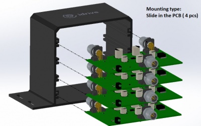
Step 1: Mount the 4 PCB Boards
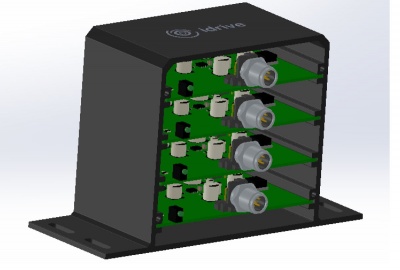
- Slide Each PCB board sequentially in the 4 slots, making sure all boards have the same orientation as in the images below
Note: Use the idrive logo on the case as a reference point when determining correct orientation
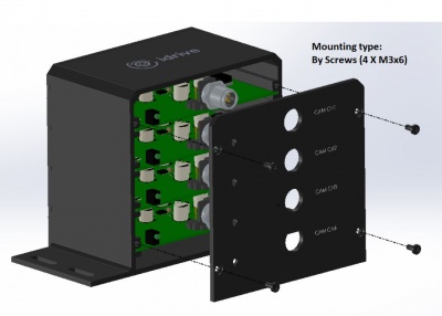
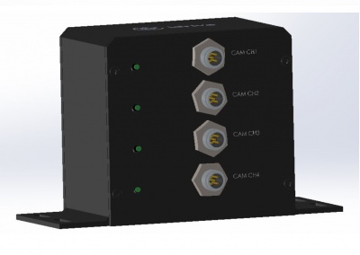
Step 2: Affix the Input Face-plate
- Place the Input face-plate flush with the input plugs and use four of the provided screws to secure it to the case
Note: The input side of the PCB has only 1 plug as well as four small led indicator lights
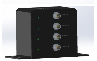
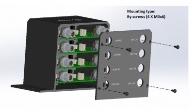
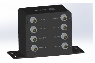
Step 3: Affix the Output Face-Plate
- Place the Output face-plate flush with the output plugs and use four of the provided screws to secure it to the case
Note: The output side of the PCB has 2 plugs
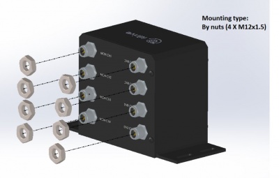
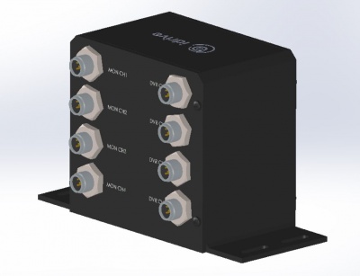
Step 4: Secure 4 Input Nuts
- Fasten the 4 input nuts tightly to the case as in the image below
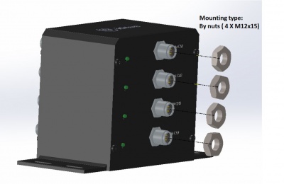
Step 5: Secure 8 Output Nuts
- Fasten the 8 output nuts tightly to the case as in the image below
Schematics and Details
Assembly Procedure PDF
File:Video Splitter Assembly Procedure.pdf
3D PCB Rendering
File:Video Splitter 3D PCB Rendering.pdf
PCB Scematic
File:Video Splitter Scematic.pdf
Adapter Cable Technical Drawings
5P Female to MiniDin 4p Male FOR Cable: File:Video Splitter 5pFemale to 4pMiniDinMale.pdf
5P Female to MiniDin 4p Female FOR Cable: File:Video Splitter 5pFemale to 4pMiniDinFemale.pdf
4P Female to GX 4P Female FOR Cable: File:Video Splitter 4pFemale to 4pGXFemale.pdf
