Difference between revisions of "Manufacturing:X2 Main Board Initial Programming and Test"
| (One intermediate revision by the same user not shown) | |||
| Line 6: | Line 6: | ||
|- | |- | ||
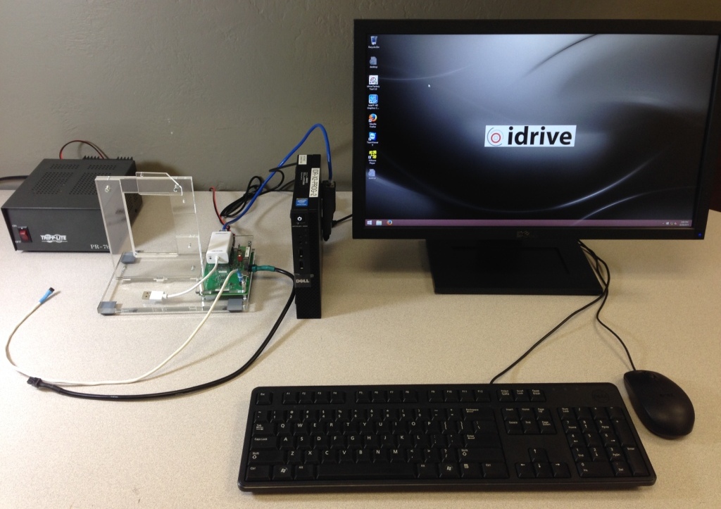
|Idrive X2 Programming Station | |Idrive X2 Programming Station | ||
| + | |- | ||
| + | |I/O Test Loopback Board | ||
|- | |- | ||
|Idrive Top Level X2 Main Board Assembly | |Idrive Top Level X2 Main Board Assembly | ||
| Line 15: | Line 17: | ||
|} | |} | ||
| − | + | <br/> | |
====Initialize Firmware Programming Station==== | ====Initialize Firmware Programming Station==== | ||
| Line 36: | Line 38: | ||
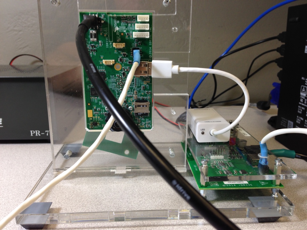
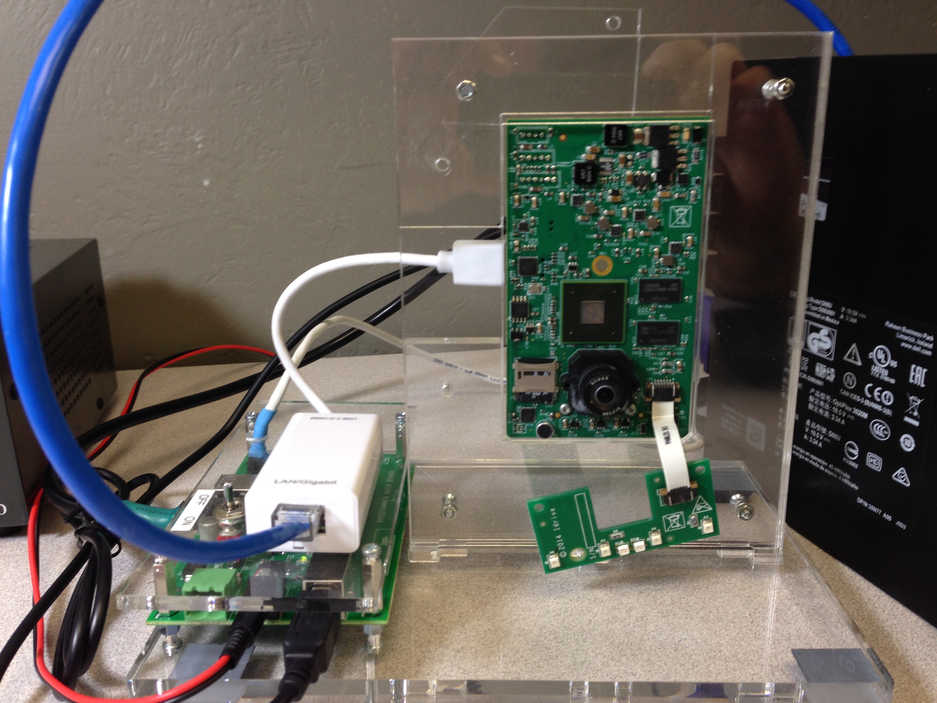
'''4.''' Connect the USB Network Adapter to the Idrive X2 Main Board. | '''4.''' Connect the USB Network Adapter to the Idrive X2 Main Board. | ||
| + | '''5.''' <span style="color: red">Plug in I/O Test board Into Accessory Connectors | ||
| + | |||
| + | ::*<span style="color: red">This adapter board is being built. For now the I/O test is bypassed | ||
| + | |||
| + | <span style="color: red"> Need a new Picture with I/O board shown | ||
[[File:idr_x2_pgmr_front.jpg|340px|]] [[File:idr_x2_pgmr_back.jpg|340px|]] | [[File:idr_x2_pgmr_front.jpg|340px|]] [[File:idr_x2_pgmr_back.jpg|340px|]] | ||
| − | + | <br\><br\> | |
====X2 Automatic Install and Configuration==== | ====X2 Automatic Install and Configuration==== | ||
| Line 45: | Line 52: | ||
Notes: The Automatic install performs the following: | Notes: The Automatic install performs the following: | ||
| − | ::* | + | ::* installs the boot loader into the X2 board. (The Kernel and filesystem are pre-installed on the 4GB SD card) |
::* gets device configuration from the Idrive AdminCenter (IP address configuration) | ::* gets device configuration from the Idrive AdminCenter (IP address configuration) | ||
| Line 91: | Line 98: | ||
====Lens Focusing==== | ====Lens Focusing==== | ||
| + | '''1.''' Select "Inside Camera" Tab and Focus the Driver Side Lens(DSL-180A) (the same side as the Processor). | ||
| + | |||
| + | ::*'''The focal length for the inside camera should be ~1.5 meters''' | ||
| − | |||
| + | '''2.''' Select "Outside camera" Tab and Focus the Road Side Lens (DSL-218A) (the same side as Power Connector). | ||
| + | |||
| + | ::*'''Focus using the provided Idrive Focus Chart. Distance to chart can be 3,6,9 feet but the farther the better. ''' | ||
| − | + | ::*Use zoom mode to ensure accurate focus | |
| − | |||
| − | |||
| − | |||
| − | |||
| − | [[File: | + | [[File:x2_lens_focus.jpg|600px|]] |
| − | |||
'''4''' Verify that the 4 IR LEDs are on (faint red glow in 4 places) | '''4''' Verify that the 4 IR LEDs are on (faint red glow in 4 places) | ||
| Line 112: | Line 119: | ||
'''5.''' If images are focused and clear and the 4 IRLeds are on click on the "Lens Focus OK" button and the focus mode will close. If the image is not clear or any IRLeds are not functioning for some reason click on the "Lens Focus Not OK" the factory tool will exit focus mode so corrective action can be taken. | '''5.''' If images are focused and clear and the 4 IRLeds are on click on the "Lens Focus OK" button and the focus mode will close. If the image is not clear or any IRLeds are not functioning for some reason click on the "Lens Focus Not OK" the factory tool will exit focus mode so corrective action can be taken. | ||
| − | '''6.''' | + | '''6.''' Once focused fix the each lens with a drop of super glue.'''Test the lenses after several minutes to ensure they have taken the glue and cannot be moved''' |
| − | '''7.''' | + | '''7.''' Remove the assembly from the test fixture, remove I/O test board |
'''8.''' Advance the Main Board Assembly to the Driver Side Case Assembly Station. | '''8.''' Advance the Main Board Assembly to the Driver Side Case Assembly Station. | ||
| − | + | <br/> | |
Latest revision as of 22:28, 28 July 2015
Idrive X2 Main Board Initial Programming
| Idrive X2 Programming & Lens Focus Materials |
|---|
| Idrive X2 Programming Station |
| I/O Test Loopback Board |
| Idrive Top Level X2 Main Board Assembly |
| Lens focus targets |
| Super Glue (for fixing lenses) (Loctite Control, Extra Time or equivalent) |
Initialize Firmware Programming Station
Setup X2 Main Board
1. Place the Idrive X2 Main board into the Device holding Fixture.
2. Connect the Power cable between the Idrive X2 Main Board and the Programming Fixture.
3. Connect the serial programming cable between the Idrive X2 Main Board and the Programming Fixture. (observe polarity)
4. Connect the USB Network Adapter to the Idrive X2 Main Board.
5. Plug in I/O Test board Into Accessory Connectors
- This adapter board is being built. For now the I/O test is bypassed
Need a new Picture with I/O board shown
<br\><br\>
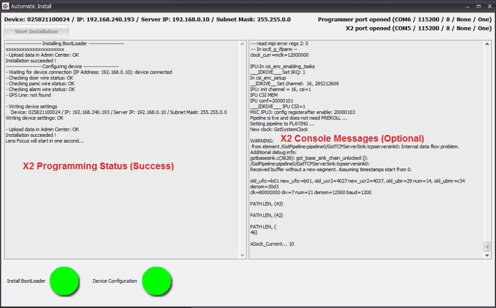
X2 Automatic Install and Configuration
Notes: The Automatic install performs the following:
- installs the boot loader into the X2 board. (The Kernel and filesystem are pre-installed on the 4GB SD card)
- gets device configuration from the Idrive AdminCenter (IP address configuration)
- Tests triggering on the yellow, blue and green wires
- provides lens focus mode so both lenses can be focused and glued
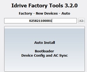
1. Click on the Factory-New Devices-Auto button ![]()
2. Scan the Bar Code label on the device to be programmed and press Enter.
(if no bar code scanner is available type the serial number from the bar code label into the serial number input field )
3. Click on the Auto Install Button and the Automatic Install window will open, Click on Start Installation
- If any of these steps fail the program will stop and give an error. Common errors are:
- Missing or corrupt OS on 4GB SD card
- Missing or corrupt storage SD card
- Serial cable not connected
- USB NIC or Internet connection missing
- I/O ports tester board missing
- Any assembly or incorrect component error
If all steps are successfully completed the program will enter into Lens Focus / LED test mode Mode.
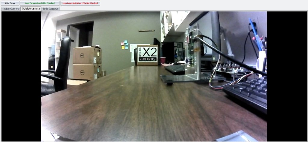
Lens Focusing
1. Select "Inside Camera" Tab and Focus the Driver Side Lens(DSL-180A) (the same side as the Processor).
- The focal length for the inside camera should be ~1.5 meters
2. Select "Outside camera" Tab and Focus the Road Side Lens (DSL-218A) (the same side as Power Connector).
- Focus using the provided Idrive Focus Chart. Distance to chart can be 3,6,9 feet but the farther the better.
- Use zoom mode to ensure accurate focus
4 Verify that the 4 IR LEDs are on (faint red glow in 4 places)
5. If images are focused and clear and the 4 IRLeds are on click on the "Lens Focus OK" button and the focus mode will close. If the image is not clear or any IRLeds are not functioning for some reason click on the "Lens Focus Not OK" the factory tool will exit focus mode so corrective action can be taken.
6. Once focused fix the each lens with a drop of super glue.Test the lenses after several minutes to ensure they have taken the glue and cannot be moved
7. Remove the assembly from the test fixture, remove I/O test board
8. Advance the Main Board Assembly to the Driver Side Case Assembly Station.
