Difference between revisions of "Boost Converter Assembly"
(Created page with "=Boost Converter Assembly= <span style="color: red">'''The Same process is used for the single channel video booster''' ==Purpose== This accessory was created to address th...") |
|||
| (35 intermediate revisions by the same user not shown) | |||
| Line 1: | Line 1: | ||
=Boost Converter Assembly= | =Boost Converter Assembly= | ||
| − | < | + | <br><br> |
==Purpose== | ==Purpose== | ||
| − | This accessory was created to address the issue of voltage drop over the 65 meter cables used on BNSF Cranes. The output voltage is set specifically for this cable | + | This accessory was created to address the issue of voltage drop over the 65 meter cables used on BNSF Cranes. |
| + | |||
| + | <span style="color: red"> '''The output voltage is set specifically for this cable length and camera type. If used for any other cable length or camera type the voltage would need to be adjusted''' | ||
[[File:idrvboost_complete.jpg|350px|]] | [[File:idrvboost_complete.jpg|350px|]] | ||
| Line 13: | Line 15: | ||
==Parts required== | ==Parts required== | ||
| − | Boost Module | + | [https://www.amazon.com/RioRand-Converter-Voltage-Adjustable-Circuit/dp/B071H39ZN5/ref=pd_lutyp_simh_2_1?_encoding=UTF8&pd_rd_i=B071H39ZN5&pd_rd_r=41994e03-2b24-40f4-9e1b-086d32b767b0&pd_rd_w=ftice&pd_rd_wg=on0aZ&refRID=BZRCJRCSYBN747MV628K&th=1 Rio Rand Boost Module] |
| + | |||
| + | |||
| + | [https://www.amazon.com/LemonBest-Waterproof-Electrical-Underground-Protection/dp/B01IQTX9YK/ref=pd_cp_60_1?_encoding=UTF8&pd_rd_i=B01IQTX9YK&pd_rd_r=bc8ab180-5de5-11e8-82d7-bd788d9ee510&pd_rd_w=kfoVD&pd_rd_wg=XODnH&pf_rd_i=desktop-dp-sims&pf_rd_m=ATVPDKIKX0DER&pf_rd_p=80460301815383741&pf_rd_r=58Z2HFNQ6ATK8VQMJXRH&pf_rd_s=desktop-dp-sims&pf_rd_t=40701&psc=1&refRID=58Z2HFNQ6ATK8VQMJXRH Enclosure] | ||
| + | |||
| + | |||
| + | Adaptor Board (Custom) | ||
| + | |||
| + | |||
| + | Camera Cable (using left over .5 meter cables we have in stock) | ||
| + | |||
| + | |||
| + | "4 Berg Sticks" | ||
| + | |||
| + | |||
| + | "2 Small Zip-Ties" | ||
| + | |||
| + | <br><br> | ||
| + | |||
| + | ==Assembly Preparation== | ||
| + | |||
| + | <br><br> | ||
| + | |||
| + | ===Prepare the Cables=== | ||
| + | |||
| + | Cut the .5 meter cable to 6 inches from the end (face) of the connector to the cut | ||
| + | |||
| + | With an Exacto Knife strip the outer insulation so that ~18mm of the 3 wires is showing | ||
| + | |||
| + | [[File:idrvboost_cableprep1.jpg|350px|]] | ||
| + | |||
| + | Unwrap the copper shielding from the Yellow video wire | ||
| + | |||
| + | [[File:idrvboost_cableprep2.jpg|350px|]] | ||
| + | |||
| + | Hold the wires in the following order; RED, White, Yellow and pull the copper shield wire so it is next to the yellow wire | ||
| + | |||
| + | separate and cut off ~6 strands of the shield and twist the rest into one "wire" | ||
| + | |||
| + | [[File:idrvboost_cableprep3.jpg|350px|]] | ||
| + | |||
| + | Tin the copper wire with solder to form the 4th wire | ||
| + | |||
| + | Using an Exacto know carefully strip the Red, White & Yellow wires so that 8mm of insulation is still exposed (this is important so that the zip tie used for strain relief and contact the outer insulation of the cable)<span style="color: red"> '''The Yellow wire is smaller than the others so ensure you do not cut any of the wire strands!!''' | ||
| + | |||
| + | Tin the 3 remaining wires with solder. | ||
| + | |||
| + | [[File:idrvboost_cableprep4.jpg|350px|]] | ||
| + | |||
| + | <br><br> | ||
| + | |||
| + | ===Prepare the Adapter Board=== | ||
| + | |||
| + | With the board silkscreen side up insert the 4 berg sticks into the holes in the corner of the adapter board | ||
| − | + | Place the Boost module on the berg sticks to help with alignment (Vertical so the boost module and adapter board are aligned) | |
| − | + | Solder the berg sticks to the '''Adapter board only''' | |
| − | + | Remove the boost module | |
| + | |||
| + | <br><br> | ||
| − | + | ==Assembly== | |
| − | + | ===Input Cable=== | |
| − | + | Feed the female cable through the Wire Gland of the enclosure | |
| − | + | Insert the wires into "J1" on the adapter board from the opposite side from the silkscreen and solder the wires | |
| − | + | Fold the cable over and secure with a zip-tie | |
| − | [[File: | + | [[File:idrvboost_inputsolder.jpg|left|250px|]][[File:idrvboost_inputziptie.jpg|250px|]] |
| − | + | <br><br> | |
| − | [[File: | + | [[File:idrvboost_inputdone.jpg|600px|]] |
<br><br> | <br><br> | ||
| + | |||
| + | ===Output Cable=== | ||
| + | |||
| + | Feed the male cable through the Wire Gland of the enclosure | ||
| + | |||
| + | Insert the wires into "J2" on the adapter board from the opposite side from the silkscreen and solder the wires | ||
| + | |||
| + | Fold the cable over and secure with a zip-tie | ||
| + | |||
| + | [[File:idrvboost_outputsolder.jpg|left|250px|]] | ||
| + | |||
| + | <br><br><br><br><br><br> | ||
| + | |||
| + | [[File:idrvboost_outputdone.jpg|600px|]] | ||
| + | |||
| + | <br><br> | ||
| + | |||
| + | ===Boost Module=== | ||
| + | |||
| + | Place the boost module on the berg sticks with the "IN+" aligned with "12V-IN" on the adapter board | ||
| + | |||
| + | Solder the 4 connections and pull the cable slack through the glands | ||
| + | |||
| + | [[File:idrvboost_boostsolder.jpg|left|400px|]] | ||
| + | |||
| + | <br><br><br><br><br><br><br><br><br><br><br><br> | ||
| + | |||
| + | [[File:idrvboost_boostdone.jpg|400px|]] | ||
| + | |||
| + | <br><br> | ||
| + | |||
| + | ==Test and adjustment== | ||
| + | |||
| + | 1)Connect leads of the voltmeter to the output of the boost module | ||
| + | |||
| + | 2)Plug the boost module into the '''DVR ONLY''' | ||
| + | |||
| + | 3)Adjust the voltage to '''between 14.25v and 14.30v''' | ||
| + | |||
| + | 4)Remove leads from the boost module and plug the output into the 65m meter cable. | ||
| + | |||
| + | 5)Measure the voulage at the camera end of the cable to ensure the boost module handles a load. | ||
| + | |||
| + | 6)Voltage without the IR Leds should be ~12.75v to 13.5v | ||
| + | |||
| + | 7)Cover the camera to engage the IR LEDs and the voltage should be ~ 11.25v - 11.5v | ||
| + | |||
| + | 8) Secure the potentiometer in place with Locktite 424 (blue) | ||
| + | |||
| + | <br><br> | ||
| + | |||
| + | ==Final Assembly== | ||
| + | |||
| + | 1)pull the slack out of the cables | ||
| + | |||
| + | 2)Place the module sideways into the case with the potentiometer side up | ||
| + | |||
| + | 3)Tighten the two glands to secure and seal the cables | ||
| + | |||
| + | 4)Place the cover on the case and secure with 4 screws. | ||
| + | |||
| + | 5) Retest the module | ||
| + | |||
| + | <br><br> | ||
| + | |||
| + | ==Label the assembly== | ||
| + | |||
| + | Label format: | ||
| + | |||
| + | Part number IDRD8BOOST14.5 is composed of: | ||
| + | |||
| + | :IDRD8BOOST (we had to call it something) | ||
| + | |||
| + | :14.5 (the voltage that the booster was set to)(this could be different is used for another cable length) | ||
| + | |||
| + | Serial Number 1806389 | ||
| + | |||
| + | :Year 18 | ||
| + | |||
| + | :Month 06 | ||
| + | |||
| + | :Number 389 | ||
| + | |||
| + | Made in USA | ||
| + | |||
| + | |||
| + | <br><br> | ||
| + | |||
| + | === | ||
Latest revision as of 22:53, 26 June 2018
Boost Converter Assembly
Purpose
This accessory was created to address the issue of voltage drop over the 65 meter cables used on BNSF Cranes.
The output voltage is set specifically for this cable length and camera type. If used for any other cable length or camera type the voltage would need to be adjusted
Parts required
Adaptor Board (Custom)
Camera Cable (using left over .5 meter cables we have in stock)
"4 Berg Sticks"
"2 Small Zip-Ties"
Assembly Preparation
Prepare the Cables
Cut the .5 meter cable to 6 inches from the end (face) of the connector to the cut
With an Exacto Knife strip the outer insulation so that ~18mm of the 3 wires is showing
Unwrap the copper shielding from the Yellow video wire
Hold the wires in the following order; RED, White, Yellow and pull the copper shield wire so it is next to the yellow wire
separate and cut off ~6 strands of the shield and twist the rest into one "wire"
Tin the copper wire with solder to form the 4th wire
Using an Exacto know carefully strip the Red, White & Yellow wires so that 8mm of insulation is still exposed (this is important so that the zip tie used for strain relief and contact the outer insulation of the cable) The Yellow wire is smaller than the others so ensure you do not cut any of the wire strands!!
Tin the 3 remaining wires with solder.
Prepare the Adapter Board
With the board silkscreen side up insert the 4 berg sticks into the holes in the corner of the adapter board
Place the Boost module on the berg sticks to help with alignment (Vertical so the boost module and adapter board are aligned)
Solder the berg sticks to the Adapter board only
Remove the boost module
Assembly
Input Cable
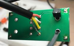
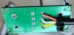
Feed the female cable through the Wire Gland of the enclosure
Insert the wires into "J1" on the adapter board from the opposite side from the silkscreen and solder the wires
Fold the cable over and secure with a zip-tie
Output Cable
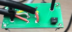
Feed the male cable through the Wire Gland of the enclosure
Insert the wires into "J2" on the adapter board from the opposite side from the silkscreen and solder the wires
Fold the cable over and secure with a zip-tie
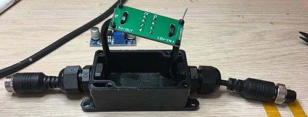
Boost Module
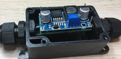
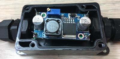
Place the boost module on the berg sticks with the "IN+" aligned with "12V-IN" on the adapter board
Solder the 4 connections and pull the cable slack through the glands
Test and adjustment
1)Connect leads of the voltmeter to the output of the boost module
2)Plug the boost module into the DVR ONLY
3)Adjust the voltage to between 14.25v and 14.30v
4)Remove leads from the boost module and plug the output into the 65m meter cable.
5)Measure the voulage at the camera end of the cable to ensure the boost module handles a load.
6)Voltage without the IR Leds should be ~12.75v to 13.5v
7)Cover the camera to engage the IR LEDs and the voltage should be ~ 11.25v - 11.5v
8) Secure the potentiometer in place with Locktite 424 (blue)
Final Assembly
1)pull the slack out of the cables
2)Place the module sideways into the case with the potentiometer side up
3)Tighten the two glands to secure and seal the cables
4)Place the cover on the case and secure with 4 screws.
5) Retest the module
Label the assembly
Label format:
Part number IDRD8BOOST14.5 is composed of:
- IDRD8BOOST (we had to call it something)
- 14.5 (the voltage that the booster was set to)(this could be different is used for another cable length)
Serial Number 1806389
- Year 18
- Month 06
- Number 389
Made in USA
