Difference between revisions of "Stonkam D8 End User Guide"
| Line 111: | Line 111: | ||
[[File:stkm_videoPlayback_viewing_controls.jpg|left|300px|]] | [[File:stkm_videoPlayback_viewing_controls.jpg|left|300px|]] | ||
| − | <br><br><br><br><br><br><br><br><br> | + | <br><br><br><br><br><br><br><br><br><br><br><br><br><br><br> |
===Diagnosing System Alarms=== | ===Diagnosing System Alarms=== | ||
Revision as of 20:40, 10 August 2017
Idrive D8 End User Guide
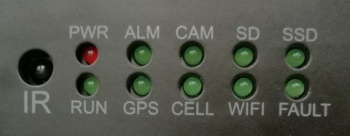
Front Panel LEDs
PWR: Power indicator - DVR is powered ON.
RUN: Working status indicator. It will flash slowly when DVR is running.
ALM: Alarm indicator. It keeps on with the record when there is Alarm-in, G-force activation or motion detection or speed or panic button event alarm.
GPS: GPS indicator. It lights up when GPS is running.
CAM: Camera indicator. It keeps on when camera is working and off when not working.
SD: SD card indicator. It blinks when recording, and keeps on when no recording, and is off when SD card in abnormal status.
SSD: SSD/HDD indicator. It blinks when recording, and keeps on when no recording, and is off when SSD/HDD in abnormal status.
CELL: Cellular indicator. It always lights up when uploading data and off when no cellular module or cellular module in abnormal status.
WIFI: WIFI indicator. It always lights up when uploading data and off when no cellular module or WIFI module in abnormal status.
FAULT: What is this?
IR This is not an LED, it is Infared Receiver is for the DVR remote control.
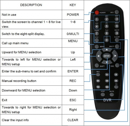
Remote Control
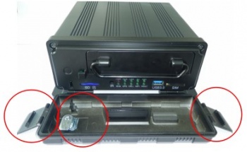
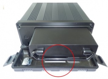
Remove Hard Disk Sled
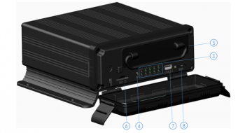
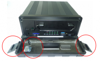
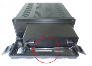
Unlock with the Key and open the two ears on the sides of the front panel, and pull down the front plate.
Remove the Hard Disk Sled by pulling on the handle.
Connecting The Monitor
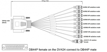
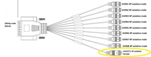
The monitor will connect through the output wire labeled AVOUT1 on the DB44 cable.
This wire is a yellow male 4Pin aviation connector (circled in yellow).
After the monitor is connected the remote is used to manipulate the menus of the device
On-Device Video Playback
Hit the pink video playback button to enter video playback mode.
A notice will appear explaining that this shuts recording off while videos are being accessed, hit ok.
Once in video playback mode you are shown a calendar.
The dates highlighted in green are the dates video has been recorded for.
To access these dates simply select them.
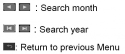
Controls While Accessing Calendar:
After selecting an appropriate date you must choose the appropriate tab for what you would like to access:
- Normal: The normal tab includes a video list of all normal video recording, Power on recording, and scheduled recordings
- Event: The event tab includes a video list of all Alarm recordings 1-8, motion detection triggered, G-force triggered, Speed Triggered, and Panic Button Triggered recordings
- Capture: The capture tab includes all screenshots captured by the user
Video Options
- Play: Plays the selected videos
- All: Selects all videos appearing on the list
- Exit: Returns you to the previous menu
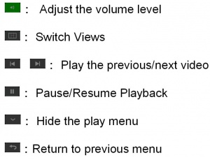
Controls While Accessing Video Playback:
Diagnosing System Alarms
| Symptom | Fault |
|---|---|
