Difference between revisions of "D8 Initial Configuration and Setup"
| Line 32: | Line 32: | ||
Place default configuration (Parameters file on the SSD) (Figure out how to use an SD card for this) | Place default configuration (Parameters file on the SSD) (Figure out how to use an SD card for this) | ||
| + | |||
| + | Looks like the hard drive needs to be powered up in the D8 so the two partitions can be created. Then put the param.xml file on it. | ||
<br><br> | <br><br> | ||
Revision as of 22:41, 21 March 2017
D8 Configuration and Setup
Document Serial number of the D8
Get the serial number from the side of the DVR. Example: 000-201-17225002
(the last 6 digits "225002" will used in settings after the param.xml file is loaded)
- device_num (Sys Setup>>Terminal>>Device ID)
- Phonenumber (Sys Setup>>Terminal>>Phone NO)
- Authentication (Sys Setup>>Terminal>>AuthNum)
Items needed
- D8 Kit
- SSD
- BNC Male to RCA Male adapter
- SIM card
Assemble System
Place default configuration (Parameters file on the SSD) (Figure out how to use an SD card for this)
Looks like the hard drive needs to be powered up in the D8 so the two partitions can be created. Then put the param.xml file on it.
Hard Drive Installation
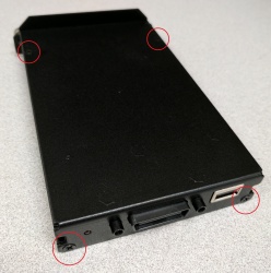
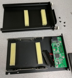
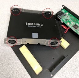
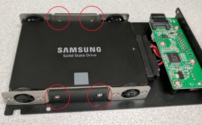
There are four screws (circled in red below) that must be removed to access the SATA port inside the hard drive sled. A picture of the inside is also given.
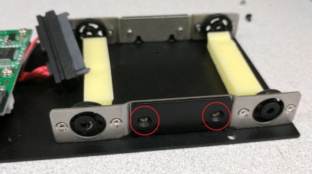
Next, remove the screws from both silver brackets, take them off of the main sled, and set them aside.
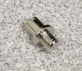
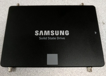
Now, locate the hard drive standoffs from the D8 accessory kit. Screw four of them into the sides of the hard drive to be installed.
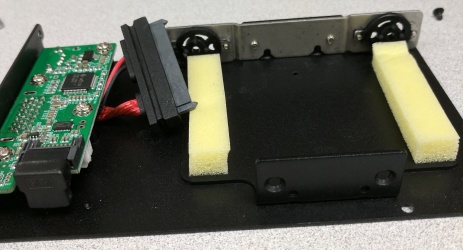
Take the silver brackets and fit them onto the hard drive standoffs. Make sure the indentation is facing inward, towards the hard drive. At this point you should also connect the SATA cable to the drive.
Finally, slide the hard drive and brackets back into place inside the sled. Re-fasten the bracket screws and reassemble the sled.
The Assembled HDD Cartridge has a USB port on it. When removed from deck you can plug the dual sided USB to USB cable into the Cartridge and a PC to view the videos. But the files are not in AVI and are in a proprietary format. You have to use the MDVRPlayer software to view and export or save.
Connect Power and 16 Pin Accessory Cable
Power - make sure it is the D8 Power cable and not the D4 cable
- Plug into +12V Power Supply
16 Pin Accessory Cable - connect
- Plug the Starcom S-Video Composite to USB Adaptor into the BNC connector
- You need a BNC to Phono Jack Adapter Sending you two AL
Remote needs Batteries
Install 2 AAA Batteries (not included with D8)
Install and Document SIM Card
Install the SIM card (what SIM, how to document etc)
It has been decided (March 15th, 2017) that we will be using PODS Systems SIMs.
the following fields are necessary to be set from the D8 Interface under Network and ......
Configure the Default Parameters using a param.xml file
Stage the param.xml file on an SD card or the SSD
Power on the D8
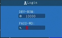
Press "Login" button on the remote
Enter the default admin password "666666" and press"OK"
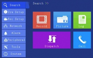
Navigate the menus using the left, right, up, down arrow buttons on the remote
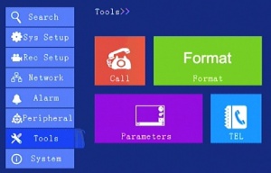
Navigate to "Tools> Parameters"
Import Parameters - reboots device to take new settings
Device Specific Settings
Power on the D8
Press "Login" on the remote
Enter the Admin Password (Default = 666666)
Set Customer/Device Specific Parameters==
- device_num (Sys Setup>>Terminal>>Device ID)
- Phonenumber (Sys Setup>>Terminal>>Phone NO)
- Authentication (Sys Setup>>Terminal>>AuthNum)
- company_name (Sys Setup>>Terminal>>Company)
- SimICCID (
Configuration "Parameters" Discussion
From Al 3/14
1. This will set ever D8 the same and there needs to be changes to each config for Terminal (which is the last 6 digits of the serial number)
3. Also I just got to setting the Alerts and only have one camera set to “EXIGENCY” – which means when disconnected send an ALARM, but I just found out I cannot duplicate the ALARM in the same window for more cameras ALARM… we get a weird alarm text when trying to save… chinglish
Resolved, When in the Alarm>IO screen press "info" and you can add other Items to enable. I added ch1.off, ch2.off etc.
- these can be setup in the param.xml file
- -Set the in "UserParam" section.
- -Then edit the "SensorAlarm Set" section, Edit the Name and "Enable" where the number 0=OFF and the number 24 is the 25th item in the pulldown menu.
To make the param.xml file for Mark, I had to change the device 6 digit number ID number. I used the last six digits of the serial number from the label on the side…
Since then I changed the unit number in the software and have not been able to connect again… I made no change to the APN data that is the same…
The DVR shows the icon as connected to the server, but I cannot get the data or tracking on the server… am working with Chinese right now…
From Al 3/15
It was unexplained. But the vehicle name must be the same as the Phone number field.
Parameters file differences 3/14 Preliminary
Comparison of Al's initial config and the default config
<KeyPara
- MD5 different
<BaseSetup
- TimeZone (Al = 7 Default = 20)
- timingtime (Al = "00:00:00" Default = "06:30:00")
- OprTimeOut (Al = 120 Default = 30)
<TerminalSetup
- device_num (Al = 225001 Default = 10000)
- Phonenumber (Al = Blank Default = 1000)
- company_name (Al = "idr" Default = Blank)
- Authentication (Al = "225001" Default = 10000)
<RecordSet
- CameraType (Al = "0" Default = 1)
<RecordSetMainChNoSet
- Resolution (Al = "2" Default = 0)
<RecordSetMirrorChNoSet
- isRec (Al = "1" Default = 0)
<SystemPowerSet
- PowerOnTime (Al = "00:00:00" Default = 06:00:00)
- PowerOffTime (Al = "00:00:00" Default = 22:00:00)
<MonitorSet
- showNum (Al = 9 Default = 8)
<NetWorkSet
- IpAddr (Al = 10.7.7.14 Default = 192.168.1.80)
- GateWay (Al = 10.7.7.1 Default 192.168.2)
- DNS1 (Al = 65.32.5.111 Default 192.168.1.2)
- DNS2 (Al = 65.32.5.111 Default 192.168.1.2)
AL:
<CenterNetwork __id="0" Enable="1" Type="0" CenterIP="72.186.112.19" ContrlPort="6608" DomainName="" />
<CenterNetwork __id="1" Enable="1" Type="0" CenterIP="10.7.7.2" ContrlPort="6608" DomainName="" />
<CenterNetwork __id="2" Enable="1" Type="0" CenterIP="0.0.0.0" ContrlPort="0" DomainName="" />
<CenterNetwork __id="3" Enable="1" Type="0" CenterIP="0.0.0.0" ContrlPort="0" DomainName="" />
<CenterNetwork __id="4" Enable="1" Type="0" CenterIP="0.0.0.0" ContrlPort="0" DomainName="" />
<CenterNetwork __id="5" Enable="1" Type="0" CenterIP="0.0.0.0" ContrlPort="0" DomainName="" />
<CenterNetwork __id="6" Enable="0" Type="0" CenterIP="0.0.0.0" ContrlPort="0" DomainName="" />
<CenterNetwork __id="7" Enable="1" Type="0" CenterIP="0.0.0.0" ContrlPort="21" DomainName="" />
Default:
<CenterNetwork __id="0" Enable="1" Type="0" CenterIP="115.159.59.201" ContrlPort="6608" DomainName="" />
<CenterNetwork __id="1" Enable="1" Type="0" CenterIP="192.168.1.10" ContrlPort="6608" DomainName="" />
<CenterNetwork __id="2" Enable="1" Type="0" CenterIP="0.0.0.0" ContrlPort="0" DomainName="" />
<CenterNetwork __id="3" Enable="1" Type="0" CenterIP="0.0.0.0" ContrlPort="0" DomainName="" />
<CenterNetwork __id="4" Enable="1" Type="0" CenterIP="0.0.0.0" ContrlPort="0" DomainName="" />
<CenterNetwork __id="5" Enable="1" Type="0" CenterIP="0.0.0.0" ContrlPort="0" DomainName="" />
<CenterNetwork __id="6" Enable="0" Type="0" CenterIP="0.0.0.0" ContrlPort="0" DomainName="" />
<CenterNetwork __id="7" Enable="1" Type="0" CenterIP="113.108.120.47" ContrlPort="21" DomainName="" /
<DialUpSet
- APN (Al = data641003 Default = 3gnet)
- UserName (Al = Blank Default = card)
- UserPwd (Al = Blank Default = card)
- SimICCID (Al & Default = "89860115851042424258") Why are these the same?
- SmsCenter (Al = Blank Default = +8613010888500)
<WifiSet
- Encrypt (Al = 2 Default = 3)
- SSID (Al = Blank Default = 888
- Pwd (Al = Blank Default = 88888888)
- IpAddr (Al = 255.255.255.255 Default = 192.168.2.10)
- SubNet (Al = 255.255.255.255 Default = 255.255.255.0)
- GateWay (Al = 255.255.255.255 Default = 192.168.2.1)
- Purpose (Al = 16 Default =0)
<AlarmSet
Al:
   <SensorAlarmSet __id="0" Name="Exigency" Enable="1" isRecord="1" LimitValue="1" HoldTime="3" DelayTime="1" linkage="32" HomePageChannel="0" />
   <SensorAlarmSet __id="1" Name="OFF" Enable="0" isRecord="0" LimitValue="1" HoldTime="3" DelayTime="1" linkage="0" HomePageChannel="0" />
   <SensorAlarmSet __id="2" Name="OFF" Enable="0" isRecord="0" LimitValue="1" HoldTime="3" DelayTime="1" linkage="0" HomePageChannel="0" />
   <SensorAlarmSet __id="3" Name="OFF" Enable="0" isRecord="0" LimitValue="1" HoldTime="3" DelayTime="1" linkage="0" HomePageChannel="0" />
   <SensorAlarmSet __id="4" Name="OFF" Enable="0" isRecord="0" LimitValue="1" HoldTime="3" DelayTime="1" linkage="0" HomePageChannel="0" />
   <SensorAlarmSet __id="5" Name="OFF" Enable="0" isRecord="0" LimitValue="1" HoldTime="3" DelayTime="1" linkage="0" HomePageChannel="0" />
   <SensorAlarmSet __id="6" Name="OFF" Enable="0" isRecord="0" LimitValue="1" HoldTime="3" DelayTime="0" linkage="0" HomePageChannel="0" />
   <SensorAlarmSet __id="7" Name="OFF" Enable="0" isRecord="0" LimitValue="1" HoldTime="3" DelayTime="1" linkage="0" HomePageChannel="0" />
   <SensorAlarmSet __id="8" Name="IO9" Enable="0" isRecord="0" LimitValue="1" HoldTime="3" DelayTime="1" linkage="0" HomePageChannel="0" />
   <SensorAlarmSet __id="9" Name="IO10" Enable="0" isRecord="0" LimitValue="1" HoldTime="3" DelayTime="1" linkage="0" HomePageChannel="0" />
   <SensorAlarmSet __id="10" Name="IO11" Enable="0" isRecord="0" LimitValue="1" HoldTime="3" DelayTime="1" linkage="0" HomePageChannel="0" />
   <SensorAlarmSet __id="11" Name="IO12" Enable="0" isRecord="0" LimitValue="1" HoldTime="3" DelayTime="1" linkage="0" HomePageChannel="0" />
   <SensorAlarmSet __id="12" Name="IO13" Enable="0" isRecord="0" LimitValue="1" HoldTime="3" DelayTime="1" linkage="0" HomePageChannel="0" />
   <SensorAlarmSet __id="13" Name="IO14" Enable="0" isRecord="0" LimitValue="1" HoldTime="3" DelayTime="1" linkage="0" HomePageChannel="0" />
   <SensorAlarmSet __id="14" Name="IO15" Enable="0" isRecord="0" LimitValue="1" HoldTime="3" DelayTime="1" linkage="0" HomePageChannel="0" />
   <SensorAlarmSet __id="15" Name="IO16" Enable="0" isRecord="0" LimitValue="1" HoldTime="3" DelayTime="1" linkage="0" HomePageChannel="0" />
Default:
   <SensorAlarmSet __id="0" Name="IO1" Enable="0" isRecord="0" LimitValue="1" HoldTime="3" DelayTime="1" linkage="0" HomePageChannel="0" />
   <SensorAlarmSet __id="1" Name="IO2" Enable="0" isRecord="0" LimitValue="1" HoldTime="3" DelayTime="1" linkage="0" HomePageChannel="0" />
   <SensorAlarmSet __id="2" Name="IO3" Enable="0" isRecord="0" LimitValue="1" HoldTime="3" DelayTime="1" linkage="0" HomePageChannel="0" />
   <SensorAlarmSet __id="3" Name="IO4" Enable="0" isRecord="0" LimitValue="1" HoldTime="3" DelayTime="1" linkage="0" HomePageChannel="0" />
   <SensorAlarmSet __id="4" Name="IO5" Enable="0" isRecord="0" LimitValue="1" HoldTime="3" DelayTime="1" linkage="0" HomePageChannel="0" />
   <SensorAlarmSet __id="5" Name="IO6" Enable="0" isRecord="0" LimitValue="1" HoldTime="3" DelayTime="1" linkage="0" HomePageChannel="0" />
   <SensorAlarmSet __id="6" Name="IO7" Enable="0" isRecord="0" LimitValue="1" HoldTime="3" DelayTime="1" linkage="0" HomePageChannel="0" />
   <SensorAlarmSet __id="7" Name="IO8" Enable="0" isRecord="0" LimitValue="1" HoldTime="3" DelayTime="1" linkage="0" HomePageChannel="0" />
   <SensorAlarmSet __id="8" Name="IO9" Enable="0" isRecord="0" LimitValue="1" HoldTime="3" DelayTime="1" linkage="0" HomePageChannel="0" />
   <SensorAlarmSet __id="9" Name="IO10" Enable="0" isRecord="0" LimitValue="1" HoldTime="3" DelayTime="1" linkage="0" HomePageChannel="0" />
   <SensorAlarmSet __id="10" Name="IO11" Enable="0" isRecord="0" LimitValue="1" HoldTime="3" DelayTime="1" linkage="0" HomePageChannel="0" />
   <SensorAlarmSet __id="11" Name="IO12" Enable="0" isRecord="0" LimitValue="1" HoldTime="3" DelayTime="1" linkage="0" HomePageChannel="0" />
   <SensorAlarmSet __id="12" Name="IO13" Enable="0" isRecord="0" LimitValue="1" HoldTime="3" DelayTime="1" linkage="0" HomePageChannel="0" />
   <SensorAlarmSet __id="13" Name="IO14" Enable="0" isRecord="0" LimitValue="1" HoldTime="3" DelayTime="1" linkage="0" HomePageChannel="0" />
   <SensorAlarmSet __id="14" Name="IO15" Enable="0" isRecord="0" LimitValue="1" HoldTime="3" DelayTime="1" linkage="0" HomePageChannel="0" />
   <SensorAlarmSet __id="15" Name="IO16" Enable="0" isRecord="0" LimitValue="1" HoldTime="3" DelayTime="1" linkage="0" HomePageChannel="0" />
<SubStreamSet
- bitRate (Al = "400" Default = 160)
- targetFrame (Al = ="25" Default = 4)
<UserParam
AL:
intParam0="255" intParam1="255" intParam2="255" intParam3="255" intParam4="255" intParam5="255" intParam6="255" intParam7="255" doubleParam="0.000000" charParam=""
Default:
intParam0="0" intParam1="0" intParam2="0" intParam3="0" intParam4="0" intParam5="0" intParam6="0" intParam7="0" doubleParam="0.000000" charParam=""
Things we may need/want to set
<SystemInfo Product_List_info , Manufacturer
<SecuritySet
- AdminPassword (Default 666666)
- UserPassword (Default 000000)
<Front0sdSet
- <ChlName __id="0" ChlName="CH1" (Change "CH1" to "Crane front Left" etc?)
Installation Issues
Documentation needed from installation
Vehicle name
what else?
Standard installation
May be a client by client thing
Connect what? Don't connect what?
Monitor Information
We are shipping a 7" monitor with the first 3 D8s.
Voltage input 9v - 35vdc, 5W
Wiring:
- Red 9-35vdc
- Black Gnd
- Yellow - video1
- Yellow - Video2
- Blue - Rear View
Camera Connections
On the Back Panel
AV IN #1 connector - Black - CH1 Yellow = CH2
AV IN #2 connector - Black - CH3 Yellow = CH4
AV IN #3 connector - Black - CH5 Yellow = CH6
AV IN #4 connector - Black - CH7 Yellow = CH8
