Difference between revisions of "FIRMWARE LOADING AND TEST PROCEDURES"
| Line 132: | Line 132: | ||
https://cds.sun.com/is-bin/INTERSHOP.enfinity/WFS/CDS-CDS_Developer-Site/en_US/-/USD/ViewProductDetail-Start?ProductRef=jdk-6u23-oth-JPR@CDS-CDS_Developer | https://cds.sun.com/is-bin/INTERSHOP.enfinity/WFS/CDS-CDS_Developer-Site/en_US/-/USD/ViewProductDetail-Start?ProductRef=jdk-6u23-oth-JPR@CDS-CDS_Developer | ||
| + | <br/> | ||
====Required Tools and supplies==== | ====Required Tools and supplies==== | ||
Revision as of 12:10, 4 September 2012
Important Information
- The 50PIN connector on the Adaptor board that connects to the unit under test is recommended for only 50 plug-in/plug-out operations by the manufacturer. It is recommended that for each 50 Idrive X1 devices/boards to have 1 adapter.
The absence of electric contact is the No 1 error generator in the programming process!. If something doesn't work, first thing change the adaptor!
- All SD cards need to be unlocked (all SD cards have a lock/unlock switch). It depends on the SD Cards‟ provider whether or not the card needs to be formatted. In all cases if the SD Card needs formatting do not use the quick version.
- Each Idrive X1 motherboard will be uniquely paired to one wifi module and one remote button that are assigned to each other during the process. Under no circumstances can you use them with another idrive X1 board! If you need to do that you need to reformat the SD card and perform the installation process from the beginning (the Idrive SN is the WiFi MAC). Never reuse a Wifi Module after Station 8 because this will create a duplicate serial number (Wifi MAC address) in the global center.
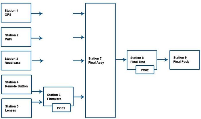
Assembly Station Workflow Chart
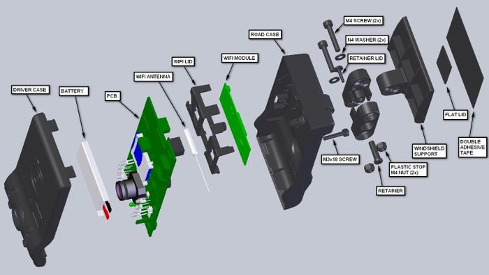
Exploded View of an idrive X1
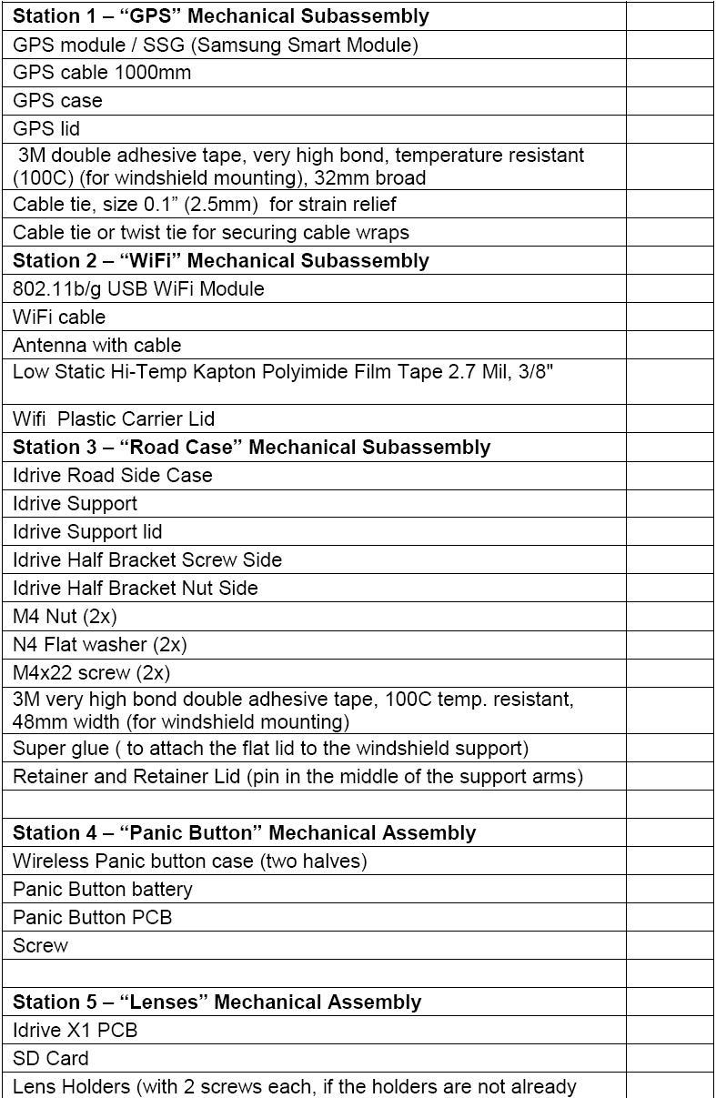
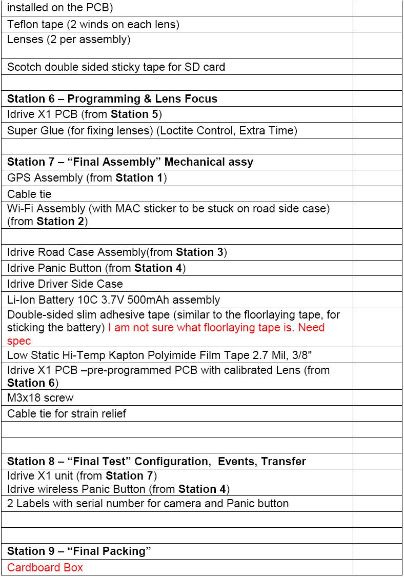
Materials Requirement by Station
Equipment Requirements and Setup
Short List
- 2 computers with Windows XP or better, Windows 7 Professional preferred
- Software and special files - provided by Idrive
- Cables (USB, parallel, network crossover etc.)
- Idrive X1 Firmware Programming Fixture
- Idrive X1 Programming adaptor board(s) (maximum 50 insertions/extractions for each)
- Idrive X1 Final Test Station Board
- Power supply 12V, 1A ( for firmware programming Station 6)
- Power supply 12V, 6A ( for Final Test Station 8)
- Label Printer (if necessary)
- Lens test charts
- Wireless router
Firmware Programming Station – (Station 6) Setup
Hardware Setup
- Computer -Windows XP or better, Windows 7 Professional recommended
- Min. requirements: 1GB RAM, 100 GB HDD, 2 Network adaptors (NICs), parallel port
- 2 Monitors recommended - need to support 1600X1200 screen resolution
- Windows Settings: autorun disabled, User Account Control disabled
- Internet connection - the internet connection is required for logging of firmware programming for each device
- Network Adapters LAN settings:
Connection one for the Programming Fixture (must use crossover cat5 cable)
IP address: 192.168.1.200 and 192.168.0.10
Subnet Mask: 255.255.0.0
Default gateway: 192.168.1.1
Connection two is for the local network with access to internet:
DHCP or as required by location
- Firmware Programming Fixture (See Appendix for detail)
- Programming Fixture to idrive X1 adaptor cable assembly
- USB Port, Serial Port (optional) from computer to Firmware Programming Fixture
- Parallel Port from computer to Firmware Programming Fixture
- Cat5 CROSSOVER cable from computer to Firmware Programming Fixture
- Cat5 regular cable to internet connection
- 12V/1A supply connected to Firmware Programming Fixture
- SD card reader – primarily for RMA activity to recover events from the SD card
ATTENTION! Use two addresses (IPs) for the interface connected to the fixture: 192.168.0.10 for Reglaj_V3.jar and 192.168.1.200 for programming the Idrive X1 Board.
Steps to add a second address at the Network Connection:
- Right Click on the network connection
- Internet Protocol -> Proprieties -> Advanced -> Add
- IP: 192.168.0.10 and Subnet Mask: 255.255.0.0
- OK -> OK -> OK -> Close
- Now, your computer is configured to communicate with the camera through Reglaj.jar (192.168.0.10) and through putty/idriveprog(192.168.1.200).
Software Setup
- TeamViewer V5.1 (http://www.teamviewer.com ) - personal license
- H-JTAG program installed (http://www.hjtag.com/download.html), version V0.9.2
- NAND configuration file for H-Flasher (nand.hfc)(idrive supplied)
- Winagents TFTP server program installed and configured (http://www.winagents.com/en/downloads/download-tftp-server.php )
- C:/arm/tftp that should contains files: u-boot ( boot loader), uImage (kernel) and filesystem.yaffs ( filesystem) (idrive supplied)
- Reglaj_V3.jar application (live cameras view for focusing lenses)(idrive supplied)
- A HyperTerminal application – Putty (http://www.putty.org )
- Idrive Firmware Programmer Application Version “July 06 2010” (idrive supplied)
- SDFormat tool the ( http://www.sdcard.org/consumers/formatter_3/eula ) DO NOT USE THE QUICK FORMAT Use the “Full(rewrite) option!
- Java Platform
Required Tools and supplies
- 2 Lens test targets (for the Driver side lens the focal length should be about 1 meter, for the Road side the lens should be focused as far as possible)
- Loctite Super Glue, “Control – Extra Time”
Final Test Station– (Station 8) Setup
Hardware Setup
- Computer - Windows XP or better, Windows 7 Professional recommended
- Min. requirements: 1GB RAM, 100 GB HDD, 2 Network adaptors (NICs)
- Windows settings: autorun disabled, User Account Control disabled - please see Config Windows 7 section of this document
- Network Adapters LAN settings:
Connection one for the Programming Fixture (must use crossover cat5 cable)
IP address: 192.168.0.10
Subnet Mask: 255.255.0.0
Default gateway: 192.168.0.1
Connection two for local network with access to internet: DHCP or as required by location
- Idrive Final Test Station Board ( See Appendix for detail)
- USB Port from computer to Final Test Programming Fixture
- Cat5 regular cable to internet connection
- Cat5 regular cable to a LAN port of wireless routing device
- 12v/6a power supply into Final Test Programming Fixture
- SD card reader
- Monitor
Wireless router Setup
- LAN IP address 192.168.0.1
- Network Mask 255.255.0.0
- Default Gateway 192.168.0.1
- SSID bwifi
- No DHCP
- No DNS
- No encryption
- No WAN settings (not in use)
Software Setup
- TeamViewer V5.1 (http://www.teamviewer.com ) - personal license
- Idrive Factory Device Tool ( Idrive supplied)
- Idrive Factory Control Center (player application for final test)(installed with Device tool)
Required Tools and supplies
- Screwdrivers
- Tweezers
- Side Cutting pliers
- Allen wrench
Process Stations Step By Step
Process Station 1 – GPS Subassembly
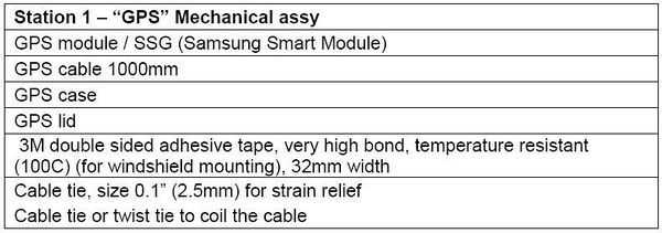
1. Attach the cable tie to the cable (about 10 mm from the 6 PIN GPS connector), in a way that it will not block the closing of the GPS Lid
2. Attach GPS cable to the GPS module
3. Mount GPS module into the GPS Case with the ceramic antenna facing you.
4. Close the case with the GPS Lid.
5. Add the 3M double adhesive tape on the GPS Lid.
6. Arrange the cable with a cable tie
GPS assembling scheme
GPS module position in case
Process Station 2 – Wifi Subassembly
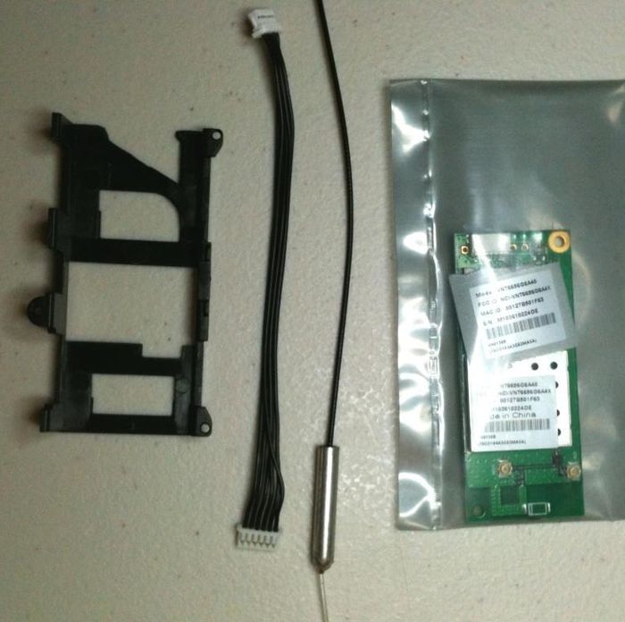
1. Remove the label with the Serial Number and save for outside of the idrive case (Station 7).
2. Connect the WiFi Cable to WiFi module. Avoid overlapping the wires.
3. Add Antenna to WiFi module on MAIN connector as shown.
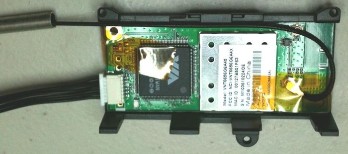
4. Place the Wifi and antenna into the Wifi cover and route the antenna cable as shown.
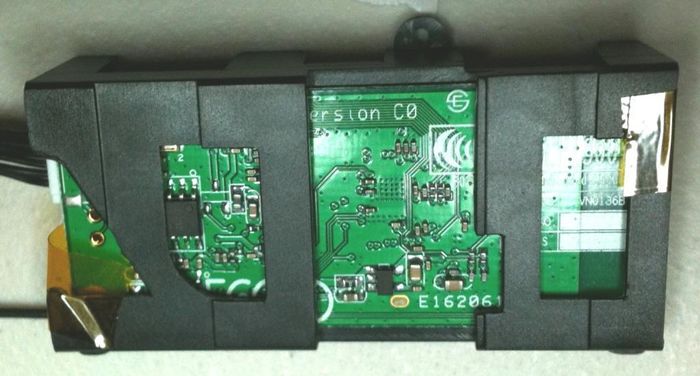
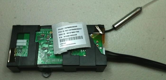
5. Apply two pieces of Kapton tape to secure the wifi module to the plastic wifi carrier. The tape should never touch any portion of the PCB or circuitry. One piece must attach to the metal can with the sticker on it and cross over the antenna connection and touch nothing but plastic on the other side as shown. The second piece of tape should touch only the top of the chips and wrap around to the other side and touch only plastic as shown. This care must be taken so as not to interfere with the wifi performance!
6. Attach the second serial number label to the plastic case with the original tape attached. The module is now ready for assembly into the road case (Station 7).
Process Station 3 – Road Case Subassembly
1. Attach the Flat Lid to the Windshield support using Super Glue. (Ensure there is a flat surface)
2. Stick the 3M double sided tape on the flat surface of the Bracket to cover the entire surface area. Trim the edges of the tape with a scalpel.
3. Attach the two Half Brackets with the Retainer and Retainer Lid. Press the retainer pins together to full seat them.
4. Attach the mated Brackets to the Road Case using a screw (M4x22), one M4 nut and one N4 washer.
5. Attach the support on the other end of the brackets as shown in the picture.
File:Assy.jpg File:Road case.jpg
Process Station 4 – Remote Panic Button
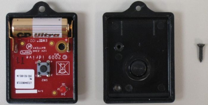
1. Mount the PCB in the case (the one without button)
2. Insert the battery between the two metallic connections
3. Mount the second half of the case and secure with the screw
4. Press the button and verify that the LED illuminates and turns off. (Verify that the plastic button has enough clearance so as not to be continuously holding down the switch once assembled)(LED illuminated)
Process Station 5 – Lenses, SD Card Assembly ~ 1minute
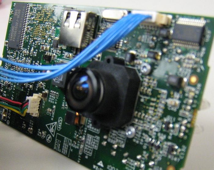
1. Mount the Lens Holders
2. Attach the SD Card to the Idrive X1 PCB. Use Scotch double sided tape on the bottom to secure the card in the socket.
3. Screw the two lenses into the Lens Holders on each side of the mother board
Process Station 6 – Programming Station Initialization
Open and Configure H-JTAG application
1. Open H-JTAG application on the PC – This programs the boot loader code on K9S1208 NAND FLASH.
2. If the H-JTAG application asks for Updates - select NO (very important).
3. Connect an idrive X1 Board to the fixture
4. Turn fixture power on (Switch S6 to the Left)
5. Turn IGNITION on (Switch S5 Right)
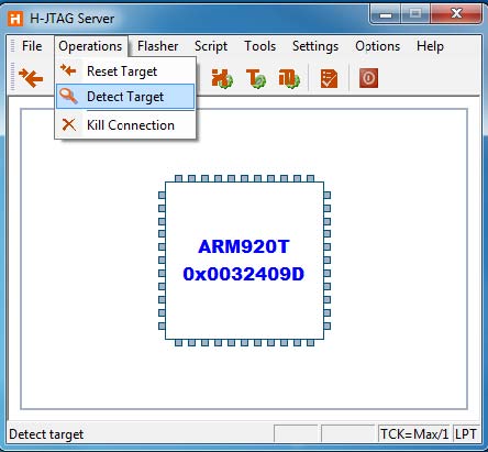
6. Click on the Operations menu, then click Detect Target. The system should display „ARM920T‟ as shown below.
Open and Configure H-Flasher application
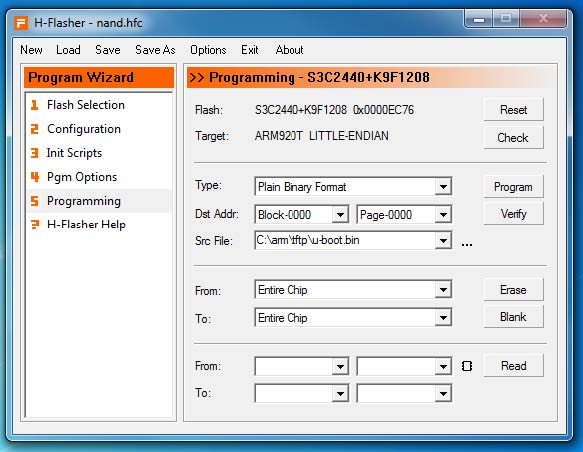
7. Open H-Flasher application on the PC – one time step
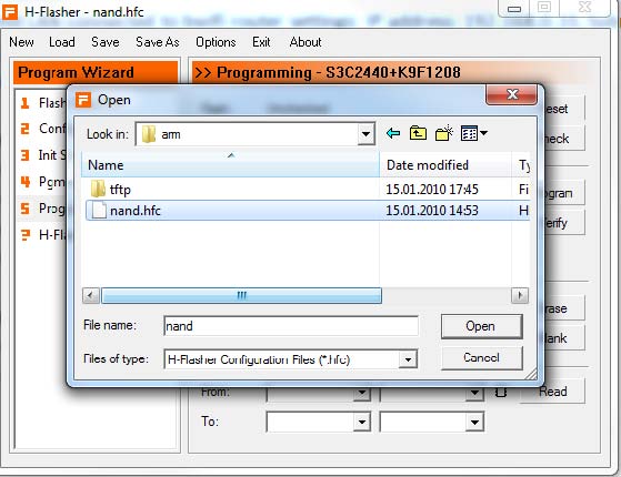
8. Press Load button from the top menu - one time step
9. Select the nand.hfc file (c:\arm\nand.hfc) - one time step
10. Select u-boot.bin (c:\arm\tftp\u-boot.bin) in the „Src File‟ box using browse button to the right of the Src File box
11. Keep H-Flasher open for the entire programming process. The settings that you have entered will remain in the H-Flasher boxes, even if you power down the PC.
Open and Configure idriveprog application
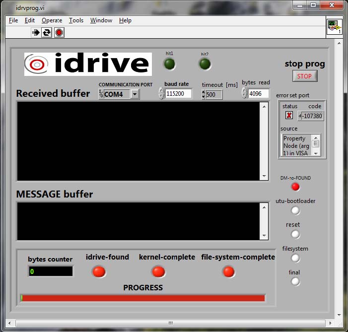
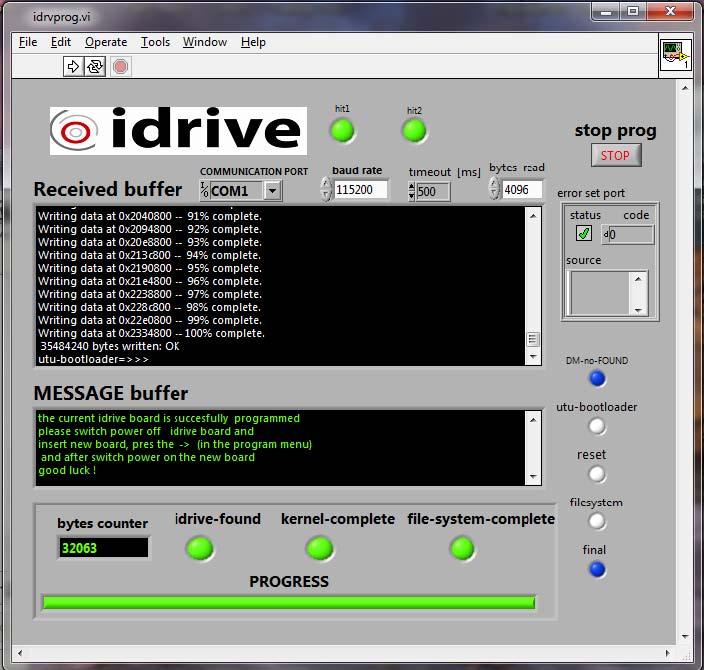
12. Open Idriveprog program and change COM 4 to your COM number. (Verify in Control Panel/Devices/Ports) Ensure the baud rate is set to 115200.
Open Reglaj_V3.jar Program for Lens Focus
13. Open Reglaj_V3.jar on the computer, and keep it open for the entire programming process.
14. The Firmware Programming Station is now ready to process idrive X1 boards
Process Station 6 - Step by Step Programming Idrive X1 Board
Setup Device ~15 seconds
1. Check that all the switches are in OFF position.
2. Place the Idrive X1 board in to the Programming Device Holder.
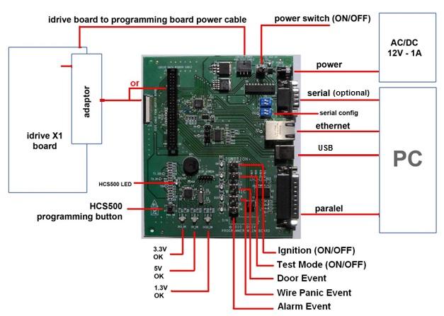
3. Connect the Power cable between the Idrive X1 Board and the Programming Fixture.
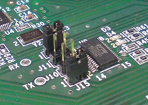
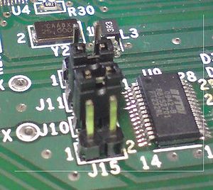
4. Connect the Adaptor between the Idrive X1 Board (J10) and the Programming Fixture.
5. Power ON the Programming Fixture (S6) (MAIN POWER ONLY) (LEFT is ON).
6. Check the 5V, 3V3 and 1V3 - all 3 LEDs must be illuminated (Green or Orange).
Program the HCS500 Remote Panic Button receiver ~ 2 seconds
7. Program the HCS500 - Press the HCS500 button (SW1) on Programmer board for programming HCS500. The BLUE LED will blink during programming.
Program the JTAG boot loader on the Camera ~20 Seconds
8. Turn the IGNITION switch (S5) to ON (on the programming board) (RIGHT is ON)
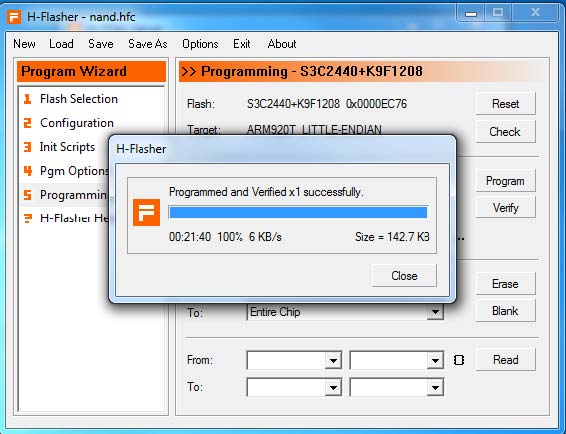
9. Click the Program button in the H-Flasher window. If an error is displayed, click the program button an additional time.
10. A progress bar window will show the status.
11. At the end the message "Programmed and verified X1 successfully" will indicate that the programming was completed successfully
12. Press Close.
13. Turn the IGNITION switch (S5) OFF (on the Programming Fixture).
Install Kernel and File System ~2:40 seconds with 4GB SD card
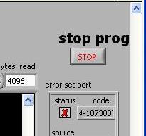
14. Press the Stop button in the idriveprog program.
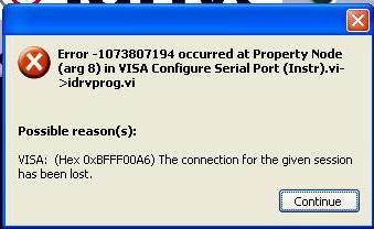
15. Press the run contiuosly and then click continue in the error window that pops up. (This is not really and error and can be ignored)
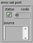
16. Verify the status box has a green check mark in it
17. Turn on the IGNITION switch (S5) to begin programming of the idrive firmware. The text field should shown in the following picture is what you should see when successfully finding the idrive unit. If there are “T”s as in the second picture this indicates a timeouts trying to talk to the unit. The most likely causes is a dead device or the programming adaptor need to be better connected. In both of these pictures the “checksum bad” can be ignored.
18. When each portion of the kernel and the filesystem loading completes successfully the red status dots for each will turn green.
19. Turn the IGNITION switch (S5) OFF
Lens Focusing ~ 45 Seconds to start program + ~30 seconds each lens - ~2:00 total
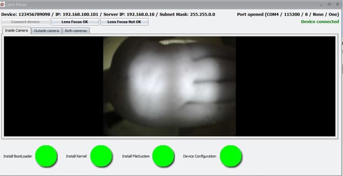
20. Turn the TEST switch (S3) to ON (LEFT) and turn IGNITION switch (S5) to ON (RIGHT) ( the Idrive X1 board will enter into the Test Mode and after about 45 seconds it will start sending video to Firmware Station when the LEFT LED is flashing RED/GREEN in a ~1 second intervals. Video will appear in the Reglaj_V3.jar window)
21. Focus camera 1 (Driver Side) (the one on the same side of the camera as the LEDs).
22. Focus camera 2 (Road Side) (the one on the side of the camera without LEDs).
Verify That the IR LEDS are working
1. Use a camera phone or camera and view the IR LEDs and verify that they are all on.
2. Turn the POWER, IGNITION and TEST switches to OFF.
3. Disconnect the power cable and the adapter
Secure Lenses
1. Fix the road lens with a drop of super glue.
2. Fix the driver lens with a drop of super glue.
3. Verify that the lenses can not move.
4. Advance the board to the next station.
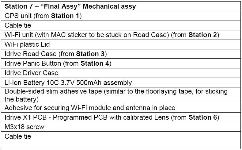
Process Station 7 – Final Assembly
1. Insert the GPS cable through the GPS rectangular hole and add the cable tie at about 50 mm from the connector to provide strain relief. (For GPS Cable assemblies equipped with a round cable this may not be necessary since the cable is so tight in the hole.)
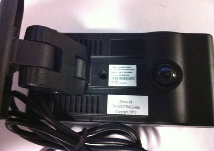
2. Remove the SN sticker from the WiFi module and stick it on the center of the back of the case, see the picture. (discard the piece of paper)
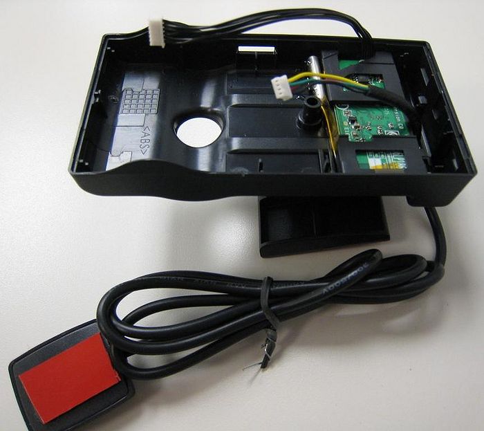
3. Place the Wifi assembly (From Station 2) into the Road Case and align it with the 3 pins molded into the case.
4. Fix the Wifi assembly to the Road Case using Kapton tape in order to prevent movement. The tape must be placed from the plastic wifi carrier across the fat metal potion of the antenna to the road case. Ensure nothing other than plastic touches the thin metal portion of the antenna and that the thin portion of the antenna is straight.
Picture is incorrect! No tape on thin part of antenna!
5. Connect the GPS module connector then the WiFi connector to the main board (Idrive PCB)
6. Insert Idrive PCB into the Road Case starting with the bottom hook and then the upper hook, press it until it clicks in and is secure. Use tweezers to deflect the top hook so that excess pressure is not used on the motherboard. Ensure that the wifi cable does not obstruct the USB connector opening.
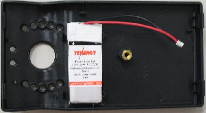
7. Take the Driver Side Case and attach the battery to it using the slim double adhesive tape as shown.
8. Connect the battery to the connector (J3) on the main board PCB.
9. Close the case starting with the top hooks. Ensure that the LEDs are aligned with the holes in the Driver Side Case and do not get bent and that they protrude through the case evenly. Ensure that the battery wires are not pinched in between the case halves or blocks the panic button programming switch opening. When the case is properly closed there should be no gap in the seam between halves of the case.
10. Fix the case with the central screw in the back.
Process Station 8 – Final Test Station Initialization
1. Open the Idrive Factory Device Tool application and keep it open for the entire testing Start the Idrive Device Tool in Automatic Mode
2. Be sure that the correct USB communication port is selected. ( Verify in Control Panel/Devices/Ports if you are not sure)
3. Open the Idrive Factory Control Center (username: admin password: admin)
4. Turn ON the wireless router or access point
Process Station 8 - Final Testing of Idrive X1
Automatic Mode ~5:20 with single camera
Note - Manual Mode is used in conjunction with Automatic mode to test shock and panic events. There is no automatic way to press the panic button or shake the camera(s)
1. Turn Off the Power Switch (Right Position)
2. Connect the Idrive X1 power cables from the Fixture to the camera(s)
3. Turn ON the Power Switch (LEFT Position) (The 6 Ignition LEDs will light up RED)
4. Push the “Automatic Mode” button and the process will start (12V ON and IGNITION LEDS turn GREEN)
5. All attached cameras will be booted (~37 seconds)
6. Sequentially, each camera‟s ignition will be turned off for configuration. If the device is configured correctly then after 25 seconds the camera will shut off and the next camera will begin configuration. If the device is not configured correctly there will be an error beep after 45 seconds and the next camera will begin the configuration process
7. If the device fails to connect to the Device Tool or if there is no device attached to that location in the fixture you may push the “Manual Mode” button to advance to the next camera.
 ** Only push the “Manual Mode” button to advance to the next camera/location after the current camera has completely shut down (both of its LEDs are off) (The skipped camera will not be booted in the next step for wired events testing)
8. After all cameras have been configured they will be automatically turned on again for wired events and transfer testing.
9. After ~75 seconds from the beginning of reboot the three wired events will be activated at a 30 second intervals.
10. After the wired events are recorded the cameras will sequentially enter into transfer mode (ORANGE Left GREEN Right LEDs) one by one at a 25 second intervals.
11. 25 Seconds after the last camera finishes transferring there will be a final beep if all 6 cameras have been successfully tested. If any camera fails a test there will be a beep after 100 seconds. The failing device will be shown in the Factory Device Tool.
12. Using the Idrive Control Center Factory Version verify that the images from both sides of the cameras have good, clear, full, bright image and are correctly focused.
13. Turn Off the Power Toggle Switch (Right Position)
Manual Mode portion ~5:00 with single camera
14. Turn on the Power Toggle Switch (Left Position) (The 6 Ignition LEDs will light up RED)
15. Push the “Manual Mode” button (Manual Mode LED will turn on)
16. Turn on 12V to the Cameras by Pressing the 12V ON/OFF Pushbutton (12V LED will Turn on)
17. Turn on the Ignition for each camera by pressing the corresponding “Ing.” Push Button
18. Wait ~30 sec. for the camera to initialize (Both LEDs must turn Solid Green)
19. Gently shake the first camera to create a shock event and observe the LEFT LED to be RED and the RIGHT LED to be GREEN indicating the camera is recording.
20. When both LEDs return to GREEN use a paperclip and depress the Remote Panic programming button and hold it until the LEDs are RED on the LEFT and GREEN on the Right.
21. Within 5 seconds press the remote panic button two times. Each time the RIGHT LED will flash ORANGE.
22. When BOTH LEDs return to GREEN press the panic button for the first camera and observe the LEFT LED to be RED and the RIGHT LED to be GREEN indicating the camera is recording.
23. Place the label with the camera‟s serial number on the back of the Remote and on the back of the camera.
24. Once BOTH LEDs turn GREEN press the ignition button for the camera to enter transfer mode ( LEFT LED ORANGE and RIGHT LED GREEN)
25. Verify the events transferred successfully in the Factory Device Tool...
26. Repeat steps 19- 25 for each camera.
27. Turn Off the Power Switch (Right Position)
28. Disconnect the power cables from the idrive devices.
29. Advance the Idrive devices to the next station.
Full Manual Mode
1. Turn Off the Power Toggle Switch (Right Position)
2. Connect the Idrive X1 power cables from the Fixture to the cameras
3. Start the Idrive Factory Device Tool in Manual Mode
4. Turn on the Power Toggle Switch (Left Position) (The 6 Ignition LEDs will light up RED)
5. Push the “Manual Mode” button (Manual Mode LED will turn on)
6. Turn on 12volts to the Cameras by Pressing the 12V ON/OFF Pushbutton (12V LED will Turn on)
7. Turn on the Ignition for the first camera by pressing the corresponding “Ing.” Push Button
8. Wait ~30 sec. for initialization - Both LEDs must turn Solid Green.
9. Wait >10 sec.
10. Press the “Ing. 1” pushbutton (IGNITION OFF on the first camera) and wait until the camera connects with the Idrive Factory Device Tool.
11. Select “Configure Device” to program the device to the default idrive standard configuration
12. The Camera will shut off ( initial configuration complete for this device)
13. Repeat Steps 7 – 12 for each camera connected to the fixture
14. After all the connected devices are configured (all of them turned off), Press the” Ign” pushbutton for each and wait until all of the devices have GREEN-GREEN LEDs (~30 seconds).
15. Press the Door Event Button and verify the Left LED turns RED during the event and returns to a GREEN-GREEN condition for each device)
16. Press the Alarm Event Button and verify the Left LED turns RED during the event and returns to a GREEN-GREEN condition for each device)
17. Press the W_Panic Event Button and verify the Left LED turns RED during the event and returns to a GREEN-GREEN condition for each device)
18. Shake each Idrive device to create a shock event and verify the Left LED turns RED during the event and returns to a GREEN-GREEN condition for each device)
19. Press Ing. 1 (IGNITION OFF on the first camera - the first Idrive X1 device will switch to Transfer Mode. (Orange Left and GREEN Right LED)
20. Wait ~ 30 Seconds and repeat steps 19 & 20 for each device
21. After the transfer(s) is complete, both LEDs will turn OFF (on all 6 devices), go to the Idrive Factory Control Center player and play the event.
22. Check that the images from both sides of the cameras have good, clear, full, bright image and are correctly focused.
23. Turn Off the Power Switch (Right Position)
24. Disconnect the power cables from the idrive devices.
25. Advance the Idrive devices to the next station.
Process Station 9 – Final Inspection and Packing
Final Inspection:
1. The correct placement of the adhesive tape
2. The correctitude of the assembly
3. No spots, no scratches etc.
4. The existence of the label SN on the back of the case
5. Matching Serial number on the back of the Remote Panic Button
Each Idrive X1 Kit needs to have one each of the following:
1. Idrive X1 full unit
2. Idrive Panic Button
3. Alcohol wipe
4. Idrive Power Cable
Appendix
The Idrive Firmware Programmer Reference
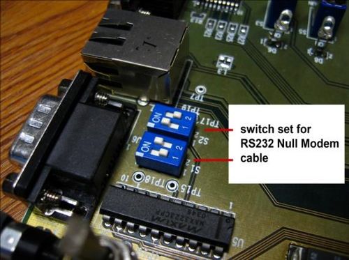
- Set Serial for null modem cable RS232:
- Idrive X1 Programming Holder (= “Holder”)
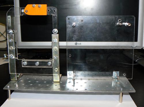
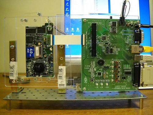 Holder completely assembled, with Idrive PCB in position
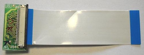
Idrive X1 Board to Programming Board Adapter
Attention! The 50PIN connector on the Adaptor board is recommended for only 50 plug-in/plug-out operations by the part manufacturer. It is recommended one adaptor be used for no more than 50 Idrive X1 devices/boards. Multiple adaptors must be built to support the size of the camera lot. The adaptor PCBs can be used over again by replacing the connector which connects to the device being programmed.
The faulty electrical connection is the No 1 error generator in the programming process!
Idrive Final Test Station Programmer Reference
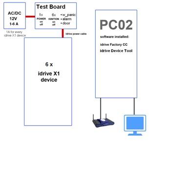
1. Connect a 12V – 6A power supply at the green terminal block.
2. Connect the USB Cable
3. Connect the 6 Idrive Power Cables
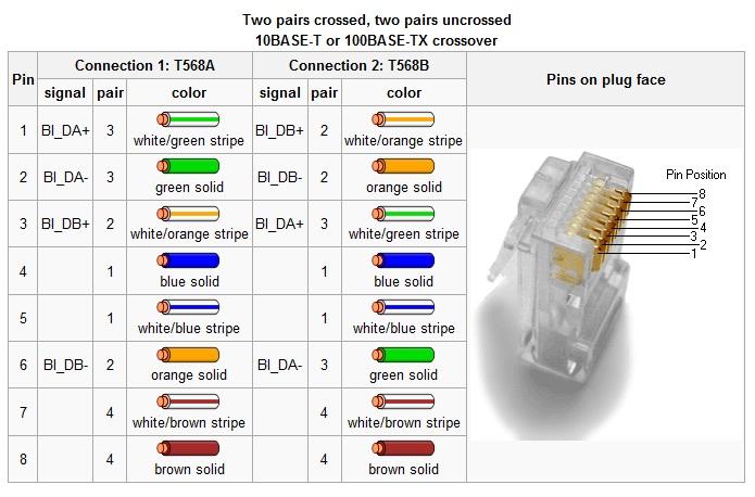
Cat5e Crossover Cable pinouts
Program installation Notes
- Install the Idrive Factory Control Center (Factory CC) Application (transfer and player application for final test)
1. Run setup.exe
2. Follow the instructions on the screen.
3. Finish/Close
4. The setup will place a shortcut on the desktop.
- Install TeamViewer - during setup you need to choose the Personal license installation!
- Install the H-JTAG Application:
1. Unzip the "H-JTAG V0.9.2.zip" file
2. Run the "H-JTAG V0.9.2.exe" file
3. Follow the installation instructions
4. The setup will place H-JTAG and H-Flasher shortcuts on the desktop
5. Delete the extra shortcuts
6. H-JTAG settings LPT/USB selection – LPT
- Install TFTP Server
1. Accept the agreement
2. Install Complete version
3. Start> Programs>WinAgents TFTP Server 4>TFTP Server Manager
4. Click OK and Start Server
5. Select Manage Virtual Folders icon and point to C:\arm\tftp
- Install Idriveprog
6. Run setup in the directory Idrive programming tools\installer\volume\setup
7. Run Setup for NI-Visa\ NIVISAruntime.msi file
8. Add shortcut to the desktop for Idriveprog c:\Program Files\Idriveprog\Idriveprog
9. run the program Idriveprog
10. press the STOP PROG
11. Change the COM4 port with your COM number
12. Press -> for start program
- Install Idrive Device Tool
1. Run setup.exe
2. Follow the instructions on the screen
3. Finish/Close
4. The setup will place shortcut on the desktop
- Install Reglaj_V3.jar application (live cameras view for focusing lens)
1. Place the folder in a known location
2. Create a shortcut on the desktop that points to Reglaj_V3.jar file
- Copy the nand.hfc file into C:/arm/tftp folder.
- Copy u-boot, uImage and filesystem.yaffs files into C:/arm/tftp
