Difference between revisions of "Configure VPN Client"
| Line 1: | Line 1: | ||
| − | ==Information Requirements== | + | ==MicroTIC VPN Solution== |
| + | |||
| + | <br\><br\> | ||
| + | |||
| + | ==Client Side== | ||
| + | |||
| + | <br\><br\> | ||
| + | |||
| + | ===Information Requirements=== | ||
'''Static Internet connection''' information for remote customer site (where Transfer point is to be installed) | '''Static Internet connection''' information for remote customer site (where Transfer point is to be installed) | ||
| Line 23: | Line 31: | ||
<br\><br\> | <br\><br\> | ||
| − | ==Initial Configuration Setup== | + | ===Initial Configuration Setup=== |
| + | |||
| + | <br\><br\> | ||
| − | ===Set up RB751U-2HnD Router for initial configuration=== | + | ====Set up RB751U-2HnD Router for initial configuration==== |
Document the MAC addresses range from the bottom of the unit. IE 00:0C:42:AE:F2:7C - 00:0C:42:AE:F2:81 (5 addresses). These will be used to connect to the device and be logged in AdminCenter. | Document the MAC addresses range from the bottom of the unit. IE 00:0C:42:AE:F2:7C - 00:0C:42:AE:F2:81 (5 addresses). These will be used to connect to the device and be logged in AdminCenter. | ||
| Line 41: | Line 51: | ||
<br\><br\> | <br\><br\> | ||
| − | ===Connect using Winbox=== | + | ====Connect using Winbox==== |
Download and install Winbox [http://download2.mikrotik.com/winbox.exe Configuration tool for RouterOS]. | Download and install Winbox [http://download2.mikrotik.com/winbox.exe Configuration tool for RouterOS]. | ||
| Line 71: | Line 81: | ||
<br\><br\><br\><br\> | <br\><br\><br\><br\> | ||
| − | ==Upgrade OS and Firmware== | + | ===Upgrade OS and Firmware=== |
Obtain the latest versions (V6.x) from the MicroTik [[http://www.mikrotik.com/download |download]] site | Obtain the latest versions (V6.x) from the MicroTik [[http://www.mikrotik.com/download |download]] site | ||
| Line 99: | Line 109: | ||
<br\><br\> | <br\><br\> | ||
| − | ==Setup using Restore configuration file (Recommended)== | + | ===Setup using Restore configuration file (Recommended)=== |
| − | ===Load Idrive Standard configuration=== | + | ====Load Idrive Standard configuration==== |
[[File:rb751_files.jpg|600px|thumb]] | [[File:rb751_files.jpg|600px|thumb]] | ||
| Line 129: | Line 139: | ||
<br\><br\><br\><br\><br\><br\> | <br\><br\><br\><br\><br\><br\> | ||
| − | ===Set Customer/Location Specific Settings=== | + | ====Set Customer/Location Specific Settings==== |
| − | ====Static Internet IP Address==== | + | =====Static Internet IP Address===== |
Click IP >Address to open the Address list form. Double Click on address to edit. All three interface addresses are shown open here. You should only need to change the ether1 address. | Click IP >Address to open the Address list form. Double Click on address to edit. All three interface addresses are shown open here. You should only need to change the ether1 address. | ||
| Line 169: | Line 179: | ||
<br\><br\> | <br\><br\> | ||
| − | ====Set SSTP Dial Out address==== | + | =====Set SSTP Dial Out address===== |
Set the Dial Out address (Static IP address of the base stations internet connection)This is the number that the Transfer Point "calls" to contact the base station. | Set the Dial Out address (Static IP address of the base stations internet connection)This is the number that the Transfer Point "calls" to contact the base station. | ||
| Line 177: | Line 187: | ||
<br\><br\> | <br\><br\> | ||
| − | ====Set Timezone for customer location==== | + | =====Set Timezone for customer location===== |
Set the timezone. The Date and time will be set by NTP (Network Time Protocol) when connected to the internet | Set the timezone. The Date and time will be set by NTP (Network Time Protocol) when connected to the internet | ||
| Line 185: | Line 195: | ||
<br\><br\> | <br\><br\> | ||
| − | ==Network Cable Connections== | + | ===Network Cable Connections=== |
EHT1 - Internet | EHT1 - Internet | ||
| Line 199: | Line 209: | ||
<br\><br\> | <br\><br\> | ||
| − | ==Advanced Configuration (no config file)== | + | ===Advanced Configuration (no config file)=== |
<br\><br\> | <br\><br\> | ||
| − | ===Interfaces configuration=== | + | ====Interfaces configuration==== |
Select "Interfaces" from the left menu and enable both "wlan1" and "ppp-out1". | Select "Interfaces" from the left menu and enable both "wlan1" and "ppp-out1". | ||
| Line 212: | Line 222: | ||
<br\><br\> | <br\><br\> | ||
| − | ====PPP configuration==== | + | =====PPP configuration===== |
Select "PPP" from the left menu then go to "Profiles" tab and add new profile. | Select "PPP" from the left menu then go to "Profiles" tab and add new profile. | ||
| Line 227: | Line 237: | ||
<br\><br\> | <br\><br\> | ||
| − | ====SSTP configuration==== | + | =====SSTP configuration===== |
Return to "Interface List" and add new "SSTP Client". | Return to "Interface List" and add new "SSTP Client". | ||
| Line 243: | Line 253: | ||
<br\><br\> | <br\><br\> | ||
| − | ====WLAN configuration==== | + | =====WLAN configuration===== |
| Line 253: | Line 263: | ||
<br\><br\> | <br\><br\> | ||
| − | ===Bridges configuration=== | + | ====Bridges configuration==== |
Select "Bridge" from the left menu and add new bridge. Configure the two bridges as shown. | Select "Bridge" from the left menu and add new bridge. Configure the two bridges as shown. | ||
| Line 270: | Line 280: | ||
<br\><br\> | <br\><br\> | ||
| − | ===Addresses configuration=== | + | ====Addresses configuration==== |
Use the "+"button and add the addresses as shown [[Configure_VPN_Client#Static_Internet_IP_Address|Here]] | Use the "+"button and add the addresses as shown [[Configure_VPN_Client#Static_Internet_IP_Address|Here]] | ||
| Line 276: | Line 286: | ||
<br\><br\> | <br\><br\> | ||
| − | ===Routes configuration=== | + | ====Routes configuration==== |
Add the three routes | Add the three routes | ||
| Line 292: | Line 302: | ||
<br\><br\> | <br\><br\> | ||
| − | ===NTP configuration=== | + | ====NTP configuration==== |
Network Time Protocol - keeps the time syncronized | Network Time Protocol - keeps the time syncronized | ||
| Line 300: | Line 310: | ||
<br\><br\> | <br\><br\> | ||
| − | ===3G notes from Florin=== | + | ====3G notes from Florin==== |
| Line 316: | Line 326: | ||
[[File:Mikrotik-client5.png|500px|]] | [[File:Mikrotik-client5.png|500px|]] | ||
| − | ==Functional testing troubleshooting== | + | ===Functional testing troubleshooting=== |
<br\><br\> | <br\><br\> | ||
| − | ===Initial Installation Checks=== | + | ====Initial Installation Checks==== |
<br\><br\> | <br\><br\> | ||
| − | ====Internet connection working ?==== | + | =====Internet connection working ?===== |
Connect using Winbox | Connect using Winbox | ||
| Line 336: | Line 346: | ||
<br\><br\> | <br\><br\> | ||
| − | ====connected to base station?==== | + | =====connected to base station?===== |
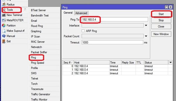
Ping the base station public IP address | Ping the base station public IP address | ||
| Line 348: | Line 358: | ||
<br\><br\> | <br\><br\> | ||
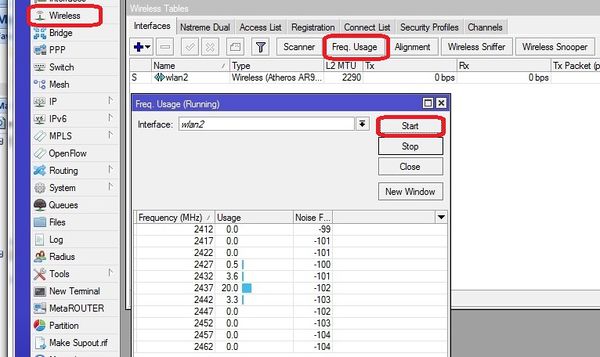
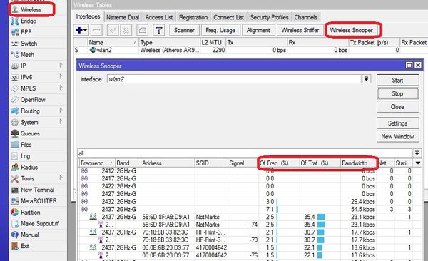
| − | ====Wifi tools / channel selection==== | + | =====Wifi tools / channel selection===== |
View other Wifi in the area | View other Wifi in the area | ||
| Line 377: | Line 387: | ||
<br\><br\> | <br\><br\> | ||
| − | ====extra APs connected and functioning?==== | + | =====extra APs connected and functioning?===== |
Ping the additional AP(s) | Ping the additional AP(s) | ||
| Line 386: | Line 396: | ||
<br\><br\> | <br\><br\> | ||
| − | ===Installation checklist=== | + | ====Installation checklist==== |
Mounting | Mounting | ||
Revision as of 17:52, 7 November 2014
MicroTIC VPN Solution
<br\><br\>
Client Side
<br\><br\>
Information Requirements
Static Internet connection information for remote customer site (where Transfer point is to be installed)
- IP Address in slash notation EX: 216.133.162.67/28 = IP Address 216.133.162.67 NetMask 255.255.255.240
- Default Gateway for connection EX: 216.133.162.65
- Network Address EX: 216.133.162.64
IP address block explained. the /28 limits the Block of addresses to 16 as follows:
216.133.162.64 - Network Address (1 address)
216.133.162.65 - Gateway Address (1 address)
216.133.162.66 - 216.133.162.79 14 useable addresses)
http://www.zytrax.com/tech/protocols/ip-classes.html#calculator
<br\><br\>
Initial Configuration Setup
<br\><br\>
Set up RB751U-2HnD Router for initial configuration
Document the MAC addresses range from the bottom of the unit. IE 00:0C:42:AE:F2:7C - 00:0C:42:AE:F2:81 (5 addresses). These will be used to connect to the device and be logged in AdminCenter.
Connect to power
Connect cat 5 cable from Port ETH5 to the NIC for Idrive wireless
- Change settings for wireless NIC on your computer to:
- -192.168.88.10
- -255.255.255.0
<br\><br\>
Connect using Winbox
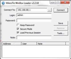
Download and install Winbox Configuration tool for RouterOS.
Run Winbox.exe or double click the icon on the desktop
- Enter the Default "Connect To" IP Address: 192.168.88.1
- Login: admin
- password: blank
- Click "Connect"
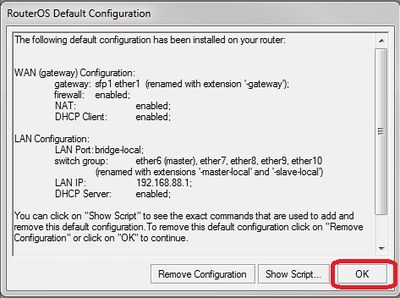
Upon initial log in the "RouterOS Default Configuration" pop-up window will appear. Choose "OK". We are not concerned about the default settings because they will be overwritten with the idrive default configuration file.
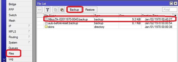
Create a backup of the default configuration just in case
Files >Backup
<br\><br\><br\><br\>
Upgrade OS and Firmware
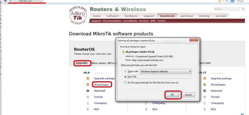
Obtain the latest versions (V6.x) from the MicroTik [|download] site
Click on the correct link for the hardware architecture (mipsbe for RB751U-2HnD)
Click on "All Packages" and click Save
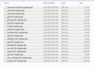
Extract all of the files from zip package
Copy the files from your computer to the Router Board by dragging and dropping all of the files into the files list in the WinBox window
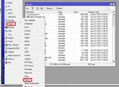
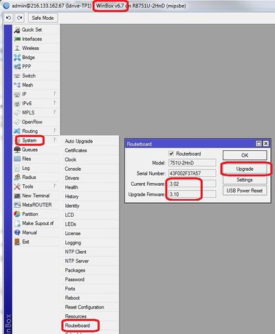
Restart the router and log back into the router and confirm that WinBox shows the new version of RouterOS and Firmware
<br\><br\>
Setup using Restore configuration file (Recommended)
Load Idrive Standard configuration
For simplicity and consistency it is better to set the routers configuration using the RouterOS backup/restore function. This "restores" the standard idrive configuration from a .backup file. This will leave only a few custom settings that are specific to the customer location(s).
- Download the most current .backup file from Admin Center
- Unzip the file to the Desktop on your computer
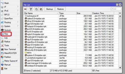
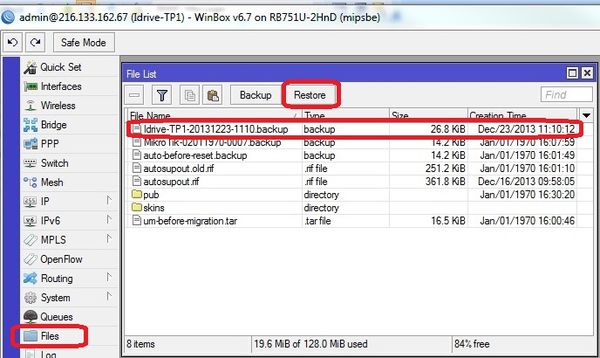
- In WinBox select “Files” from the left menu to open the Files List window.
- Use the mouse to drag and drop the configuration file from the Desktop into the Files List (uploads the file to the Router)
- Highlight the config file and click on "Restore"
The router will reboot with the new configuration. You will need to use the new IP address and password
- -The new IP address for Ports 3 - 5 will be 192.168.0.3
- -Change the IP address on your NIC to 192.168.0.10
Reconnect to the Router with the "Connect to" address of 192.168.0.3, password idrive#
<br\><br\><br\><br\><br\><br\>
Set Customer/Location Specific Settings
Static Internet IP Address
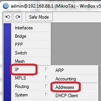
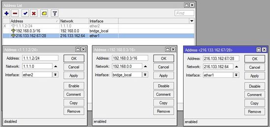
Click IP >Address to open the Address list form. Double Click on address to edit. All three interface addresses are shown open here. You should only need to change the ether1 address.
Modify the internet connection address for the customer's location.
ether1 - This must be configured prior to shipment or you will not be able to contact the Transfer Point when it is installed at the customer location!!!.
- Enter Static IP address (216.133.162.67/28 in this example)
- Enter Network Address (216.133.162.64 in this example)
- Interface "ether1"
bridge_local - No need to change unless there is more than one Remote Transfer point in the Idrive system. This is the IP address that the base station will see. Ports 3,4,5 share this address.
- IP Address 192.168.0.3/16
- Network 192.168.0.0
- Interface bridge_local
ether2 - Set by config file and does not need to be changed.
- IP Address 1.1.1.2/24
- Network 1.1.1.0
- Interface ether2
<br\><br\>
Set SSTP Dial Out address
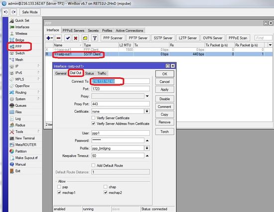
Set the Dial Out address (Static IP address of the base stations internet connection)This is the number that the Transfer Point "calls" to contact the base station.
<br\><br\>
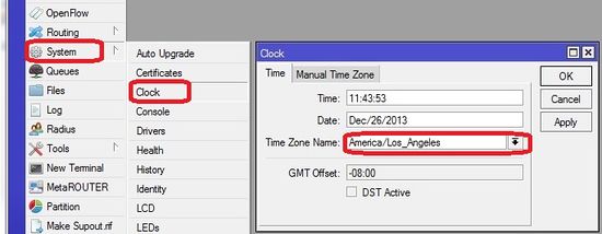
Set Timezone for customer location
Set the timezone. The Date and time will be set by NTP (Network Time Protocol) when connected to the internet
<br\><br\>
Network Cable Connections
EHT1 - Internet
ETH2 - loopback cable to ETH3
ETH3 - loopback cable to ETH2
ETH4 - Optional extra AP (192.168.0.3)
ETH5 - Optional extra AP (192.168.0.3)
<br\><br\>
Advanced Configuration (no config file)
<br\><br\>
Interfaces configuration
Select "Interfaces" from the left menu and enable both "wlan1" and "ppp-out1".
<br\><br\>
PPP configuration
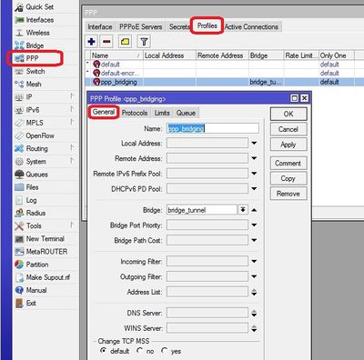
Select "PPP" from the left menu then go to "Profiles" tab and add new profile.
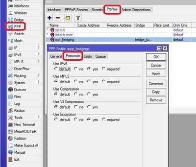
Complete the fields then select "Protocols" tab and check "yes" under "Use Encryption".
<br\><br\>
SSTP configuration
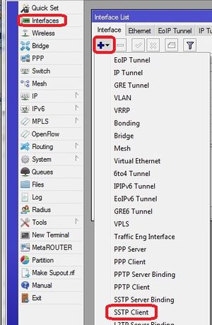
Return to "Interface List" and add new "SSTP Client".
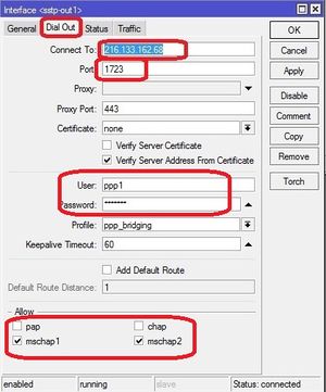
In the "Dial Out" fill "Connect To:" with the VPN Server public IP, set port to 1723, enter the user name and password that you have created on VPN Server.
Uncheck "pap" and "chap" boxes from "Allow".
If the VPN Server is configured the status will appear as connected.
If the VPN Server is not configured then check Configure VPN Server.
<br\><br\>
WLAN configuration
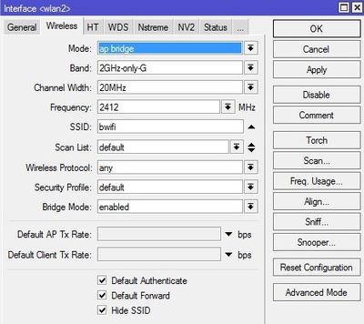
Return on "Interface List" double-click "wlan1", select "Wireless" tab and complete the fields as in picture.
<br\><br\>
Bridges configuration
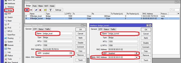
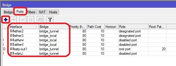
Select "Bridge" from the left menu and add new bridge. Configure the two bridges as shown.
for "bridge_tunnel" Make sure the "ARP" is disabled and enter the MAC Address: 00:00:5E:80:01:01 then select "STP" tab and check "Protocol Mode: rstp".
select "Ports" tab and add interfaces to the proper bridge as shown
<br\><br\>
Addresses configuration
Use the "+"button and add the addresses as shown Here
<br\><br\>
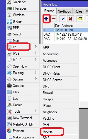
Routes configuration
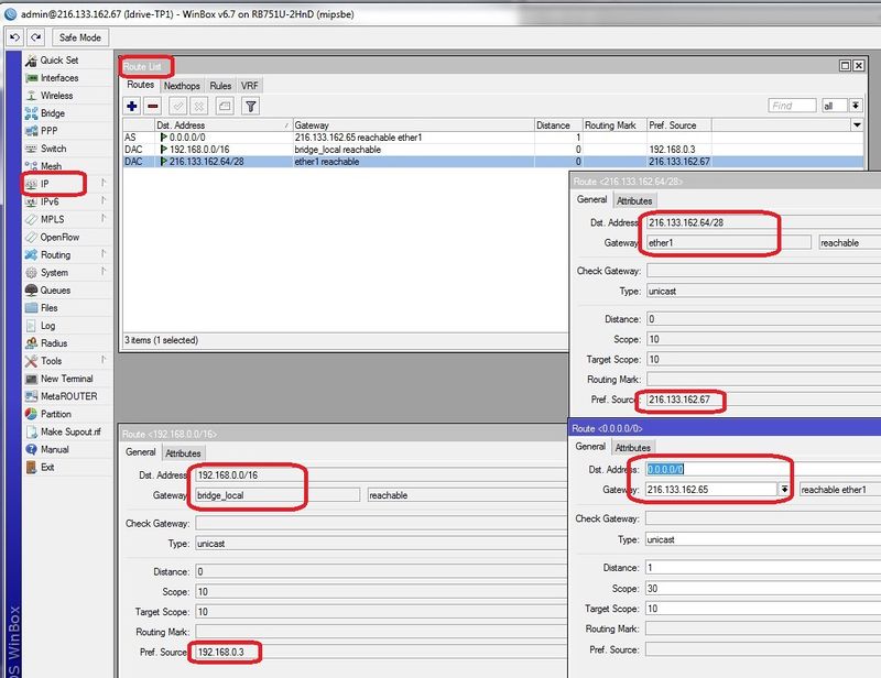
Add the three routes
route <0.0.0.0/0> - set the Gateway address for the customers internet gateway at the remote location. Leave Dst. Address all zeros.
route <192.168.0.0/16> - routes 192.168.x.x (events) traffic through the tunnel to the base station.
route <216.133.162.64/28> - Routes all internet traffic out the Ether1 interface. The address is the Network address for the remote location internet connection.
<br\><br\>
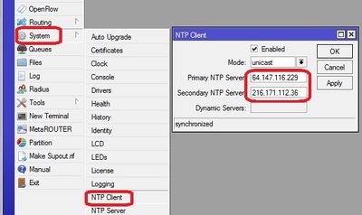
NTP configuration
Network Time Protocol - keeps the time syncronized
<br\><br\>
3G notes from Florin
Connect your 3G USB dongle and restart router.
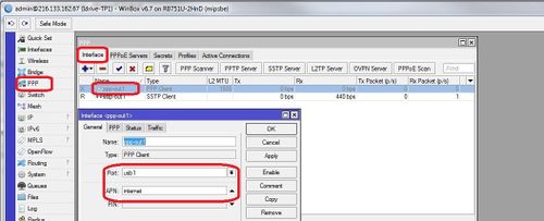
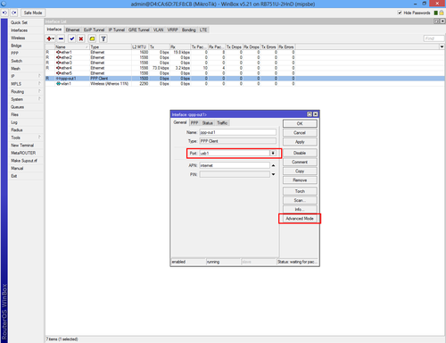
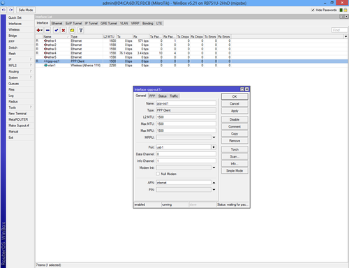
Return on "Interface List" and double-click "ppp-out1" and make sure that "usb1" option is selected. If the "Port" drop-down list is empty then your 3G dongle is not supported.
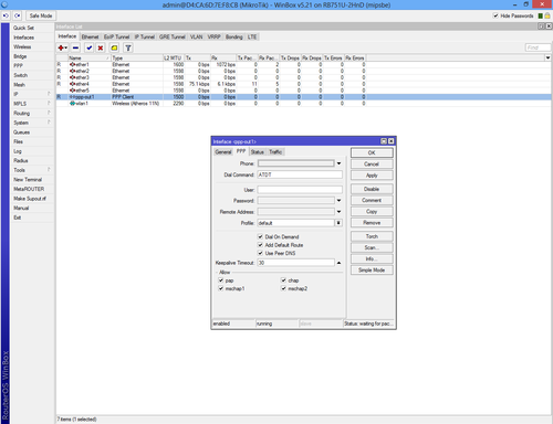
Our 3G USB worked by default without any other configuration. Click on "Advanced Mode" if your SIM does require mobile carrier configuration.
Functional testing troubleshooting
<br\><br\>
Initial Installation Checks
<br\><br\>
Internet connection working ?
Connect using Winbox
Connect using a browser
Telnet into the Terminal Point using Putty
Ping the terminal point
<br\><br\>
connected to base station?
Ping the base station public IP address
Check the structure using neighbor discovery (192.168.0.2 is at the base station end). This shows connectivity as well as the tunnel working.
<br\><br\>
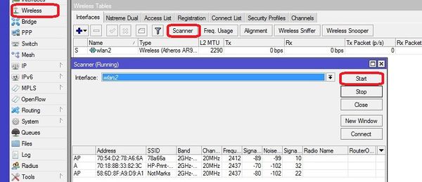
Wifi tools / channel selection
View other Wifi in the area
View the amount of traffic on each channel
<br\><br\>
extra APs connected and functioning?
Ping the additional AP(s)
<br\><br\>
Installation checklist
Mounting
Electrical Wiring
Antenna sealed with tape
Internet connection
External APs installed and connected
<br\><br\>
<br\><br\>
