Difference between revisions of "X1 Manufacturing Procedures 2013"
| Line 569: | Line 569: | ||
---- | ---- | ||
| − | ===Process Station 6 - "Final Test" (Wifi, GPS, Transfers)=== | + | ===Process Station 6 - "Final Test" (Wifi, GPS, Shock Event, Transfers)=== |
====Final Test Station Initialization==== | ====Final Test Station Initialization==== | ||
Revision as of 22:23, 14 March 2013
Important Information
- All SD cards need to be unlocked (all SD cards have a lock/unlock switch). It depends on the SD Cards‟ provider whether or not the card needs to be formatted. In all cases if the SD Card needs formatting do not use the quick version.
The power supply 12V 1A for the programming board needs to be stabilized type.
Assembly Station Workflow Chart
Materials Requirement by Station
| Station 1 – “Main Board” Assembly |
|---|
| Idrive X1 PCB |
| SD Card |
| Lens Holders (with 2 screws each) |
| Lenses (2 per assembly) |
| 3 Bar code Labels with Serial number |
| Station 2 – “WiFi” Mechanical Subassembly |
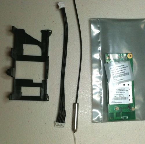
| 802.11b/g USB WiFi Module |
| WiFi cable |
| Antenna with cable |
| Low Static Hi-Temp Kapton Polyimide Film Tape 2.7 Mil, 3/8" |
| Wifi Plastic Carrier Lid |
| Double sided Tape for Antenna (Specify Type) |
| Station 3 – “Road Case” Mechanical Subassembly |
| Idrive Road Side Case |
| Idrive Support |
| Idrive Half Bracket Screw Side |
| Idrive Half Bracket Nut Side |
| M4 Nut (2x) |
| N4 Flat washer (2x) |
| M4x25 screw (2x) |
| 3M very high bond double adhesive tape, 100C temp. resistant, 48mm width (for windshield mounting) |
| Super glue ( to attach the flat lid to the windshield support) |
| Retainer and Retainer Lid (pin in the middle of the support arms) |
| Station 4 – Main Board Programming & Lens Focus |
| Idrive X1 PCB (from Station 1) |
| Super Glue (for fixing lenses) (Loctite Control, Extra Time) |
| Station 5 – “Final Assembly” Mechanical assy |
| GPS or GPRS Assembly ( Depends on Camera Version) |
| Wi-Fi Assembly (from Station 2)(with Label for case) |
| Idrive Road Case Assembly(from Station 3) |
| Low Static Hi-Temp Kapton Polyimide Film Tape 2.7 Mil, 3/8" |
| Idrive X1 PCB –pre-programmed PCB with Focused Lenses (from Station 4) |
| Idrive Driver Side Case |
| M3x18 screw |
| 1 Label with bar coded serial number for camera case |
| Station 6 – “Final Test” (Wifi, GPS, Transfers) |
| Idrive X1 unit (from Station 5) |
| Station 7 – “Final Packing” |
| Completed Idrive X1 (From Station6) |
| Idrive Power Cable harness Assembly |
| Idrive Wired Panic Button Assembly |
Equipment Requirements and Setup
Short List
- 2 computers with Windows XP or better, Windows 7 Professional preferred
- Software and special files - provided by Idrive
- Cables (USB, parallel, network crossover etc.)
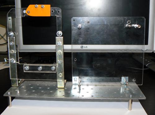
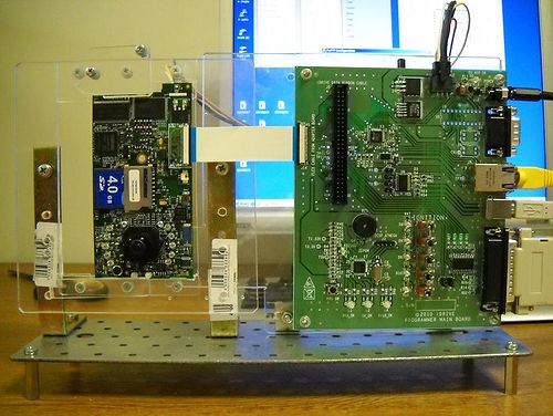
- Idrive X1 Firmware Programming Fixture
- Idrive X1 Final Test Station Board
- Stabilized Power supply 12V, 1A
- Power supply 12V, 6A
- Label Printer
- Lens test charts
- Wireless router
Firmware Programming Station Setup
Hardware Setup
- Computer -Windows XP or better, Windows 7 Professional recommended
- Min. requirements: 1GB RAM, 100 GB HDD
- 2 Network adaptors (NICs)
- 1 Monitor recommended - need to support 1600X1200 screen resolution
- Windows Settings: autorun disabled, User Account Control disabled
- Internet connection - the internet connection is required for logging of firmware programming for each device
- Network Adapters LAN settings:
- Connection one for the Programming Fixture
- IP address: 192.168.0.10
- Subnet Mask: 255.255.0.0
- Default gateway: 192.168.1.1
- Connection two is for the local network with access to internet:
- DHCP or as required by location
- Firmware Programming Fixture (See Appendix for detail)
- ASIX Network Adapter
- Mini HDMI to Mini HDMI cable - max. 1m
- USB Cable type B to type A max. 1.5m
- Cat5 regular cable to internet connection
- Cat5 regular cable to ASIX network adapter
- 12V/1A supply connected to Firmware Programming Fixture
- Power Cable 6 PIN to 6 PIN
- SD Card "Installer"
- SD card reader – primarily for RMA activity to recover events from the SD card
Software Setup and Installation
- TeamViewer (http://www.teamviewer.com ) - personal license. Install TeamViewer - during setup you need to choose the Personal license installation!
- A HyperTerminal application – Putty (http://www.putty.org )
- SDFormat tool the ( http://www.sdcard.org/consumers/formatter_3/eula ) DO NOT USE THE QUICK FORMAT Use the “Full(rewrite) option!
- Install the FTDI Driver (see FTDI Driver Installation instructions on the internal Wiki)
- Install Idrive Factory Tools
- 1. Run setup.exe
- 2. Follow the instructions on the screen
- 3. Finish/Close
- 4. The setup will place shortcut on the desktop
Required Tools and supplies
- 2 Lens test targets (for the Driver side lens the focal length should be about 1 meter, for the Road side the lens should be focused as far as possible)
- Loctite Super Glue, “Control – Extra Time”
Final Test Station – Setup
Hardware Setup
- Computer - Windows XP or better, Windows 7 Professional recommended
- Min. requirements: 1GB RAM, 100 GB HDD, 2 Network adaptors (NICs)
- Windows settings: autorun disabled, User Account Control disabled - please see Config Windows 7 section of this document
- Network Adapters LAN settings:
- Connection one for the Programming Fixture
- IP address: 192.168.0.10
- Subnet Mask: 255.255.0.0
- Default gateway: 192.168.0.1
- Connection two for local network with access to internet: DHCP or as required by location
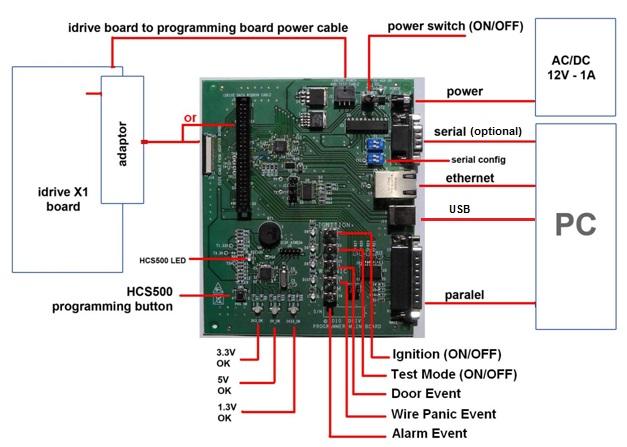
- Idrive Final Test Station Board ( See Appendix for detail)
- USB Port from computer to Final Test Programming Fixture
- Cat5 regular cable to internet connection
- Cat5 regular cable to a LAN port of wireless routing device
- 12v/6a power supply into Final Test Programming Fixture
- SD card reader
- Monitor
Wireless router Setup
- LAN IP address 192.168.0.1
- Network Mask 255.255.0.0
- Default Gateway 192.168.0.1
- SSID bwifi
- No DHCP
- No DNS
- No encryption
- No WAN settings (not in use)
Software Setup
- TeamViewer (http://www.teamviewer.com ) - personal license
- Idrive Factory Tools ( Idrive supplied)
Required Tools and supplies
- Screwdrivers
- Tweezers
- Side Cutting pliers
- Allen wrench
Process Stations Step By Step
Process Station 1 – Main board assembly
| Station 1 – “Main Board” Assembly Materials |
|---|
| Idrive X1 PCB |
| SD Card |
| Lens Holders (with 2 screws each) |
| Lenses (2 per assembly) |
| 3 Bar code Labels with Serial number |
When an Idrive X1 main board completes the SMT process there are more assembly steps needed.
1. Bar Code Labels - Unique Serial Number Labels will be pre-generated for each Main board work order. Three labels are required for each serial number(one for the main board, one for final camera case, one for the outside of the packing box). The Bar Code Label needs to be max. 22 mm x 10 mm. After SMT Assembly each Main board needs have a serial number label affixed to the SD Card Connector. This serial number will track the main board through all processes and eventually become the camera serial number.
2. Soldering of through hole/ special components (LEDs,?)
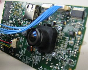
3. Mounting of the two Lens Holders Mounting to the board.
4. Inserting the lenses in the Lens Holders.
5. Insert SD Card into the SD socket.
Process Station 2 – Wifi Mechanical Subassembly
ADD New Pictures with correct antenna
| Station 2 – “WiFi” Mechanical Subassembly Materials |
|---|
| 802.11b/g USB WiFi Module |
| WiFi cable |
| Antenna with cable |
| Low Static Hi-Temp Kapton Polyimide Film Tape 2.7 Mil, 3/8" |
| Wifi Plastic Carrier Lid |
| Double sided Tape for Antenna (Specify Type) |
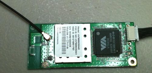
1. Connect the WiFi Cable and Antenna Cable to WiFi module. Antenna Cable must be attached to the "MAIN" connector.
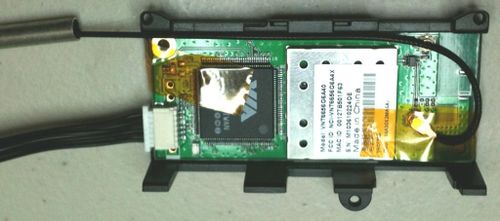
2. Place the Wifi and antenna into the Wifi cover and route the antenna cable as shown.
3. Apply two pieces of Kapton tape to secure the wifi module to the plastic wifi carrier. The tape should never touch any portion of the PCB or circuitry. One piece must attach to the metal can with the sticker on it and cross over the antenna connection and touch nothing but plastic on the other side as shown. The second piece of tape should touch only the top of the chips and wrap around to the other side and touch only plastic as shown. This care must be taken so as not to interfere with the wifi performance!
Attention! Place the antenna in to the MAIN connector on the WIFI module! Not in the AUX connector!
Process Station 3 – Road Case Mechanical Subassembly
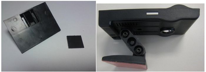
New Picture without flat lid
| Station 3 – “Road Case” Mechanical Subassembly Materials |
|---|
| Idrive Road Side Case |
| Idrive Support |
| Idrive Half Bracket Screw Side |
| Idrive Half Bracket Nut Side |
| M4 Nut (2x) |
| N4 Flat washer (2x) |
| M4x25 screw (2x) |
| 3M very high bond double adhesive tape, 100C temp. resistant, 48mm width (for windshield mounting) |
| Super glue ( to attach the flat lid to the windshield support) |
| Retainer and Retainer Lid (pin in the middle of the support arms) |
1. Stick the 3M double sided tape on the flat surface of the Bracket to cover the entire surface area. Trim the edges of the tape with a scalpel.
2. Attach the two Half Brackets with the Retainer and Retainer Lid. Press the retainer pins together to fully seat them.
3. Attach the mated Brackets to the Road Case using a screw (M4x25), one M4 nut and one N4 washer.
4. Attach the support on the other end of the brackets as shown in the picture.
Process Station 4 – Main Board Programming & Lens Focus
| Station 4 – Main Board Programming & Lens Focus Materials |
|---|
| Idrive X1 PCB (from Station 1) |
| Super Glue (for fixing lenses) (Loctite Control, Extra Time) |
Programming Station Initialization
1. Open Factory Tools Application
2. Turn fixture power on (SW1)
3. The Firmware Programming Station is now ready to process idrive X1 boards
Step by Step Programming Idrive X1 Board
Setup Device ~5 seconds
1. Place the Idrive X1 board in to the Programming Device Holder.
2. Scan the Bar Code label with the serial number (if no bar code scanner type the serial number from the bar code label into serial number input field from Idrive Factory Tools Application)
3. Connect the Power cable between the Idrive X1 Board and the Programming Fixture.
4. Connect the MINI HDMI cable between the Idrive X1 Board and the Programming Fixture.
Program the board (bootloader, kernel, filesystem, configuration)
1. Insert the SD Card Installer into the X1 board.
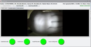
2. Press Start Installation on the Factory Tools App. You will have confirmation status for each step and the application will enter directly into the Focus Lens section if programming and configuration succeed.
Lens Focusing
1. Focus camera 1 (Driver Side) (the one on the same side of the camera as the LEDs).
2. Focus camera 2 (Road Side) (the one on the side of the camera without LEDs).
Verify That the IR LEDS are working (optional)
1. Use a camera phone or camera and view the IR LEDs and verify that they are all on.
Finish Programming
1. Press Finish button on the Factory Tools
2. Remove the SD Card Installer
3. Disconnect the power cable and the adapter
Secure Lenses
1. Fix the each lens with a drop of super glue.
2. Verify that the lenses can not move.
3. Advance the board to the next station.
Process Station 5 – Final Assembly
Need new Picture(s)with the new board
| Station 5 – “Final Assembly” Mechanical assy |
|---|
| GPS or GPRS Assembly ( Depends on Camera Version) |
| Wi-Fi Assembly (from Station 2)(With label for case) |
| Idrive Road Case Assembly(from Station 3) |
| Low Static Hi-Temp Kapton Polyimide Film Tape 2.7 Mil, 3/8" |
| Idrive X1 PCB –pre-programmed PCB with Focused Lenses (from Station 4) |
| Idrive Driver Side Case |
| M3x18 screw |
| 1 Label with bar coded serial number for camera case |
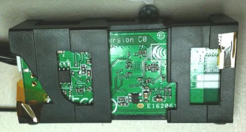
1. Place the Wifi assembly (From Station 2) into the Road Case ( From Station 3) and align it with the 3 pins molded into the case.Need correct Picture
2. Fix the Wifi assembly to the Road Case using Kapton tape in order to prevent movement. Affix the Antenna to the case using the double sided tape as shown Need correct Picture
3. Connect the WiFi module to the main board (Idrive X1 PCB)Need correct Picture
4. Place the main Board into The Road Case. Insert the bottom first and then click in the top. Use tweezers to move the top tab so that excessive force is not needed to seat the board. Ensure that the Wifi cable does not obstruct the USB connector opening or the lens.Need correct Picture
5. Place the second Bar Code Label (Serial Number) on the back of the case (make sure that the label for the case matches the label on the SD Card Connector).Need correct Picture Do we need the Wifi Label on here too for FCC etc?
6. Insert the GPS Module into the Road Case Need correct Picture
7. Connect the GPS module to the main board (Idrive X1 PCB)Need correct Picture
8. Close the case starting with the top hooks. Ensure that the LEDs are aligned with the holes in the Driver Side Case and do not get bent and that they protrude through the case evenly. When the case is properly closed there should be no gap in the seam between halves of the case.
9. Fix the case with the central screw in the back.
Process Station 6 - "Final Test" (Wifi, GPS, Shock Event, Transfers)
Final Test Station Initialization
1. Turn ON the wireless router or access point
2. Open the Event Test - Transfer and Play Section of Idrive Factory Tools application and keep it open for the entire testing.
Testing the Unit
1. Scan the Bar Code label with the serial number (if no bar code scanner type the serial number from the bar code label into serial number input field from Idrive Factory Tools Application)
2. Turn the device Idrive X1 ON - Power ON, Ignition ON.
3. Wait the initialization (aprox. 30 seconds) until the both LED turn green and gently shake the camera to create a shock event and observe the left LED to be red and the right LED to be green indicating the camera is recording.
4. When both LED return to green turn the Ignition OFF.
5. The camera device will automatically WIFI download the event to the computer station. The device will automatically show up in the connections list.
6. Press "Play events" link for each device and play the events.
Final Inspection and Packing
Final Inspection:
1. The correct placement of the adhesive tape
2. The correctitude of the assembly
3. No spots, no scratches etc.
4. The existence of the label SN on the back of the case
Each Idrive X1 Kit needs to have one each of the following:
1. Idrive X1 full unit
2. Alcohol wipe
3. Idrive Power Cable
Appendix
The Idrive Firmware Programmer Reference
- Idrive X1 Programming Holder (= “Holder”)
